GPIO configuration and use
GPIO, the full name of General-Purpose Input/Output, is a general-purpose pin that can be dynamically configured and controlled during software operation.
The following is an example of controlling the LEDs of ROC-RK3399-PC Pro. For other devices, the method is similar.
The main control of ROC-RK3399-PC Pro is RK3399, RK3399 has 5 groups of GPIO bank: GPIO0~GPIO4, each group is divided by A0~A7, B0~B7, C0~C7, D0~D7 as the number.
GPIO number calculation
The ROC-RK3399-PC Pro has two LEDs onboard as follows:
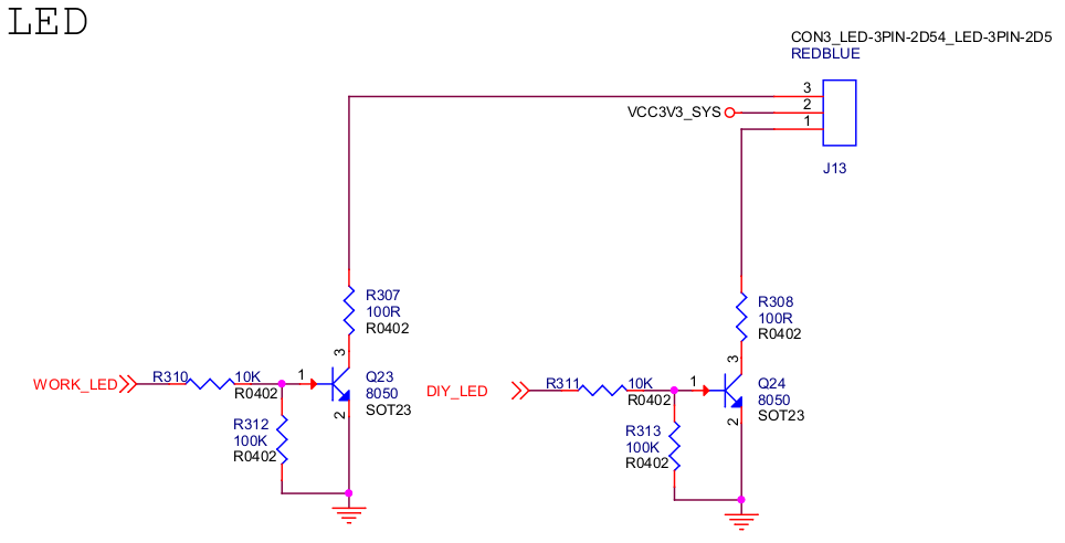
The DIY_LED net is connected to pin GPIO0_B5:

PIO pin calculation formula:
pin = bank * 32 + number
GPIO group number calculation formula:
number = group * 8 + X
For example GPIO0_B5:
bank = 0; // GPIO0_B5 => 0, bank ∈ [0,4]
group = 1; // GPIO0_B5 => 1, group ∈ {(A=0), (B=1), (C=2), (D=3)}
X = 5; // GPIO0_B5 => 5, X ∈ [0,7]
number = group * 8 + X = 1 * 8 + 5 = 13;
pin = bank * 32 + number = 0 * 32 + 13 = 13;
Note: This pin is occupied by the LED subsystem by default in the officially released firmware, so first you need to find the following node to disable it!
The ROC-RK3399-PC Pro is defined in arch/arm64/boot/dts/rockchip/rk3399-roc-pc.dtsi:
user {
        status = "disabled"; // add this line
        label = "firefly:yellow:user";
        linux,default-trigger = "ir-user-click";
        default-state = "off";
        gpios = <&gpio0 13 GPIO_ACTIVE_HIGH>;
        pinctrl-names = "default";
        pinctrl-0 = <&led_user>;
};
Then compile and reprogram the kernel firmware.
User mode uses GPIO
Apply for GPIO
echo 13 > /sys/class/gpio/export
Configure the pin direction
Check out the default pin orientation:
cat /sys/class/gpio/gpio13/direction
Configured as output direction:
echo out > /sys/class/gpio/gpio13/direction
Configure pin output level
As can be seen from the previous schematic diagram, the output high level is to turn on the LED:
echo 1 > /sys/class/gpio/gpio13/value
To turn off the LED:
echo 0 > /sys/class/gpio/gpio13/value
Device tree using GPIO
To configure GPIO in the device tree, you need to configure the function multiplexing and electrical properties of the pins
For rockchip pins, the configuration is as follows:
rockchip,pins = <PIN_BANK PIN_BANK_IDX MUX &phandle>
in:
PIN_BANK: the bank where the pin is locatedPIN_BANK_IDX: the pin number of the bank where the pin is locatedMUX: function multiplexing configuration,0means common GPIO,1-Nmeans special function multiplexingphandle: pin general configuration, such as internal pull-ups, current strength, etc., described in theDocumentation/devicetree/bindings/pinctrl/pinctrl-bindings.txtfile
Configure the GPIO0_B5 pin:
rockchip,pins = <0 13 RK_FUNC_GPIO &pcfg_pull_none>;
Meaning here:
PIN_BANKequals0PIN_BANK_IDXequals13RK_FUNC_GPIOmeans to use normal GPIO functionpcfg_pull_nonerepresents normal configuration
For LEDs, Linux defines a set of GPIO subsystems, and the configuration of the device tree is as follows:
/ {
	gpio_led: gpio-led {
		compatible = "gpio-leds";

		diy_led: diy-led {
			label = "diy-led";
			default-state = "on"; // 默认打开
			linux,default-trigger = "default-on"; // 默认触发
			gpios = <&gpio0 13 GPIO_ACTIVE_HIGH>; // 引脚设置
			pinctrl-names = "default";
			pinctrl-0 = <&diy_led_pin>; // 引用 pinctrl
		};
	};
};

&pinctrl {
	gpio-led-pin {
		diy_led_pin: diy-led-pin {
			rockchip,pins =
				<0 13 RK_FUNC_GPIO &pcfg_pull_none>;
		};
	};
};
Then compile and re-program the kernel firmware, reboot the system and you will see that the LED is lit by default.
If you want the LED to have a blinking effect, you can modify the linux,default-trigger property to achieve:
linux,default-trigger = "timer";
After configuring this property, the LED blinks every 500ms interval by default.
For more property configuration, please refer to Documentation/devicetree/bindings/leds/leds-gpio.txt.
The above device tree configuration can be found in arch/arm64/boot/dts/rockchip/firefly-gpio-demo.dtsi! Users who need it can include this file in the board device tree (remember to disable the conflicting part in rk3399-roc-pc.dtsi first):
#include "firefly-gpio-demo.dtsi"