1. User and password
1.1. Ubuntu Desktop system
After the Firefly Linux Desktop system boots up, it will automatically log in to the firefly user.
If there is a debugging serial port connected, the serial terminal automatically logs in to the root user.
Firefly user password: firefly
Root user: No root password is set by default. Firefly users configure the root password by themselves through the
sudo passwd rootcommand.
1.2. Ubuntu Minimal system
After the Firefly Linux Minimal system is booted, it will automatically log in to the root user with the password firefly
The system has added OpenGL ES, OpenCL, DRM support.
1.3. Buildroot system
User: root
password: firefly
2. ADB use
2.1. ADB
Connect the device and the host with a Type-C data cable, then enter the following commands:
adb devices
adb shell
2.2. Network ADB
Check the IP address of the development board and access the PC through the network:
adb connect + IP
adb shell
Note:
AIO-3399-JD4 / AIO-3399J needs to modify kernel/arch/arm64/boot/dts/rockchiprk3399-firefly-aiojd4.dts to support the use of ADB, set usbdrd_dwc3_0 to peripheral mode, then the usb can only be used as a slave device use.
&usbdrd_dwc3_0 {
     dr_mode = "peripheral";
};
Similarly, AIO-3399Pro-JD4 needs to modify kernel/arch/arm64/boot/dts/rockchip/rk3399pro-firefly-aioc.dts to support the use of ADB.
Then recompile and flash the Kernel.
3. linux-headers
linux-headers include header files, can make the device able to compile drivers.
3.1. How to get
3.1.1. Download from Firefly
Kernel 5.10 or Kernel 4.19 Linux-Headers: For the package download of each board, please go to the official Firefly Download page to download. After selecting the board, click the Download page, it is generally in the Resources section, and the name is linux-headers.
Kernel 6.1 Linux-Headers: By default, the SDK for kernel 6.1 will compile linux-headers into extboot.img. You can find linux-headers-6.1-arm64_arm64.deb in the /boot/ directory of the device.
3.1.2. Build from SDK
The version of headers and image downloaded above may mismatch your firmware, and they are not helpful with customization needs. So build them from SDK is recommended.
Prepare environment, get SDK and comfigure for compile, please check the specific deivce’s wiki.
Build under SDK root directory:
./build.sh kerneldeb
Output files are in SDK root directory:
linux-headers-x.xx.xxx_x.xx.xxx-xxx_arm64.deb
3.2. Install
The following takes the installation of ROC-RK3568-PC as an example:
Put deb packages in device to install, for headers, you have to compile them after installation
For device supports extboot, reboot to update kernel after installing image, then compile headers
# Install
sudo apt install ./linux-headers-4.19.172_4.19.172-189_arm64.deb

# Compile Kernel 5.10 or 4.19 Linux-Headers
sudo apt install -y build-essential python libssl-dev # Prepare
cd /usr/src/linux-headers-4.19.172
make headers_check
make headers_install
make scripts # make scripts may go wrong but it doesn't matter

# Compile Kernel 6.1 Linux-Headers
cd /usr/src/linux-headers-6.1-arm64
./scripts/builddtb.sh
3.3. Compile DTS
The Linux headers corresponding to the SDK have already packaged DTS. Customers can quickly modify and compile
DTS directly on the board without having to set up a separate development environment on the computer.
# Take ROC-RK3588S-PC to modify DTS to switch PCIE/SATA as an example:
cd /usr/src/linux-headers-6.1-arm64/
vim arch/arm64/boot/dts/rockchip/rk3588-firefly-roc-rk3588s-pc.dts

#define FF_SATA0 // M.2 slot, mux with pcie2x1l2
//#define FF_PCIE2_1L2 // M.2 slot, mux with sata0

=>

//#define FF_SATA0 // M.2 slot, mux with pcie2x1l2
#define FF_PCIE2_1L2 // M.2 slot, mux with sata0

./scripts/builddtb.sh -s

reboot
4. Export device system
When the user has completed the deployment of the working environment on one device, the current environment needs to be exported completely to deploy to other devices in batches. The current development environment can be backed up by exporting the device file system.
Exporting the device system is divided into two steps:
Export the Ubuntu root file system rootfs on the device;
Repackage the complete firmware, combine Ubuntu rootfs with other partitions where the firmware is released, complete the secondary packaging, and generate a new complete firmware.
4.1. Export device rootfs
Note that the following operations are all performed on the device side.
In the Ubuntu environment of the device, install
fireflydev:sudo apt update sudo apt install fireflydev
After installing
fireflydev, you can use theff_export_rootfsscript to export the root file system Exporting to external storage devices or the /userdata/ root directory is allowed only; exporting to other directories on the device is prohibited.!It is recommended to use a mobile hard disk with a larger capacity
The exporter does things like
apt cleanto reduce the filesystem sizeExport the root file system, for example, to the
/media/firefly/AC91-C4AE/directory (it takes a while):
ff_export_rootfs /media/firefly/AC91-C4AE/
Compress the file system, delete unnecessary blank space to reduce memory resource usage:
# Some customers said that the size of the exported rootfs is 3.3G, but actually only 3G is used, because the rootfs is not compressed
e2fsck -p -f Firefly_Ubuntu_18.04.6_rootfs.img
resize2fs -M Firefly_Ubuntu_18.04.6_rootfs.img
4.2. Second package complete firmware
Note that the following operations are all performed on the PC (x86-64 architecture).
Install the necessary packages:
sudo apt-get install lib32stdc++6Download the secondary packaging tool: firefly-linux-repack
Unzip the secondary packaging tool:
tar -xzf firefly-linux-repack.tgz
cd firefly-linux-repack
The directory is as follows:
firefly-linux-repack
    ├── bin
    │   ├── afptool
    │   └── rkImageMaker
    ├── pack.sh # packaging script
    ├── Readme_en.md
    ├── Readme.md
    └── unpack.sh # unpack script
Unpacking operation: Copy the official Ubuntu firmware to the
firefly-linux-repackroot directory, rename it toupdate.img, and execute the unpacking scriptunpack.sh. After the unpacking is complete, the partition files are in theoutputdirectory.mv /path/to/ROC-RK3566-PC_Ubuntu18.04-r21156_v1.2.4a_220519.img update.img ./unpack.sh
Packaging operation: Keep the current directory structure and file name unchanged, connect the mobile hard disk to the PC, replace
output/Image/rootfs.imgwith the Ubuntu rootfs exported earlier, and then execute the packaging scriptpack.sh.cp /media/customer/1878-4615/Firefly_Ubuntu_18.04.6_rootfs.img /path/to/firefly-linux-repack/output/Image/rootfs.img ./pack.sh
The new full firmware is
new_update.imgin the current directory.
5. GPIO configuration and use
GPIO, the full name of General-Purpose Input/Output, is a general-purpose pin that can be dynamically configured and controlled during software operation.
The following is an example of controlling the LEDs of ROC-RK3399-PC Pro. For other devices, the method is similar.
The main control of ROC-RK3399-PC Pro is RK3399, RK3399 has 5 groups of GPIO bank: GPIO0~GPIO4, each group is divided by A0~A7, B0~B7, C0~C7, D0~D7 as the number.
5.1. GPIO number calculation
The ROC-RK3399-PC Pro has two LEDs onboard as follows:
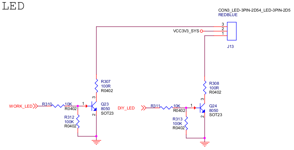
The DIY_LED net is connected to pin GPIO0_B5:

PIO pin calculation formula:
pin = bank * 32 + number
GPIO group number calculation formula:
number = group * 8 + X
For example GPIO0_B5:
bank = 0; // GPIO0_B5 => 0, bank ∈ [0,4]
group = 1; // GPIO0_B5 => 1, group ∈ {(A=0), (B=1), (C=2), (D=3)}
X = 5; // GPIO0_B5 => 5, X ∈ [0,7]
number = group * 8 + X = 1 * 8 + 5 = 13;
pin = bank * 32 + number = 0 * 32 + 13 = 13;
Note: This pin is occupied by the LED subsystem by default in the officially released firmware, so first you need to find the following node to disable it!
The ROC-RK3399-PC Pro is defined in arch/arm64/boot/dts/rockchip/rk3399-roc-pc.dtsi:
user {
        status = "disabled"; // add this line
        label = "firefly:yellow:user";
        linux,default-trigger = "ir-user-click";
        default-state = "off";
        gpios = <&gpio0 13 GPIO_ACTIVE_HIGH>;
        pinctrl-names = "default";
        pinctrl-0 = <&led_user>;
};
Then compile and reprogram the kernel firmware.
5.2. User mode uses GPIO
Apply for GPIO
echo 13 > /sys/class/gpio/export
Configure the pin direction
Check out the default pin orientation:
cat /sys/class/gpio/gpio13/direction
Configured as output direction:
echo out > /sys/class/gpio/gpio13/direction
Configure pin output level
As can be seen from the previous schematic diagram, the output high level is to turn on the LED:
echo 1 > /sys/class/gpio/gpio13/value
To turn off the LED:
echo 0 > /sys/class/gpio/gpio13/value
5.3. Device tree using GPIO
To configure GPIO in the device tree, you need to configure the function multiplexing and electrical properties of the pins
For rockchip pins, the configuration is as follows:
rockchip,pins = <PIN_BANK PIN_BANK_IDX MUX &phandle>
in:
PIN_BANK: the bank where the pin is locatedPIN_BANK_IDX: the pin number of the bank where the pin is locatedMUX: function multiplexing configuration,0means common GPIO,1-Nmeans special function multiplexingphandle: pin general configuration, such as internal pull-ups, current strength, etc., described in theDocumentation/devicetree/bindings/pinctrl/pinctrl-bindings.txtfile
Configure the GPIO0_B5 pin:
rockchip,pins = <0 13 RK_FUNC_GPIO &pcfg_pull_none>;
Meaning here:
PIN_BANKequals0PIN_BANK_IDXequals13RK_FUNC_GPIOmeans to use normal GPIO functionpcfg_pull_nonerepresents normal configuration
For LEDs, Linux defines a set of GPIO subsystems, and the configuration of the device tree is as follows:
/ {
	gpio_led: gpio-led {
		compatible = "gpio-leds";

		diy_led: diy-led {
			label = "diy-led";
			default-state = "on"; // 默认打开
			linux,default-trigger = "default-on"; // 默认触发
			gpios = <&gpio0 13 GPIO_ACTIVE_HIGH>; // 引脚设置
			pinctrl-names = "default";
			pinctrl-0 = <&diy_led_pin>; // 引用 pinctrl
		};
	};
};

&pinctrl {
	gpio-led-pin {
		diy_led_pin: diy-led-pin {
			rockchip,pins =
				<0 13 RK_FUNC_GPIO &pcfg_pull_none>;
		};
	};
};
Then compile and re-program the kernel firmware, reboot the system and you will see that the LED is lit by default.
If you want the LED to have a blinking effect, you can modify the linux,default-trigger property to achieve:
linux,default-trigger = "timer";
After configuring this property, the LED blinks every 500ms interval by default.
For more property configuration, please refer to Documentation/devicetree/bindings/leds/leds-gpio.txt.
The above device tree configuration can be found in arch/arm64/boot/dts/rockchip/firefly-gpio-demo.dtsi! Users who need it can include this file in the board device tree (remember to disable the conflicting part in rk3399-roc-pc.dtsi first):
#include "firefly-gpio-demo.dtsi"
6. Network Configuration
6.1. Ethernet port general parameter configuration
6.1.1. View Ethernet general parameters
Common parameters of Ethernet include: auto-negotiation, duplex mode and interface speed
ethtool eth0
6.1.2. Configure Ethernet general parameters
6.1.2.1. Enable or disable auto-negotiation
ethtool -s port_name autoneg { on | off }
6.1.2.2. Modify duplex mode
ethtool -s port_name duplex { half | full }
Notice:
When the Ethernet interface works in auto-negotiation mode, the duplex mode is negotiated with the peer interface by default.
When the Ethernet interface works in non-auto-negotiation mode, the duplex mode is full-duplex by default.
6.1.2.3. Modify rate
ethtool -s port_name speed { 10 | 100 | 1000 }
Notice:
When an Ethernet interface works in auto-negotiation mode, the interface rate is negotiated with the peer interface by default.
When an Ethernet interface works in non-auto-negotiation mode, the default interface rate is the maximum interface rate supported by the interface.
6.1.3. Configuration example
Manually set the interface rate of eth0 to 100 and work in full-duplex mode.
ethtool -s eth0 autoneg off
ethtool -s eth0 speed 100
ethtool -s eth0 duplex full
6.2. Manage the network with Netplan
Netplan is a utility for easily configuring networking on linux systems. You just create a YAML description of the desired network interface and each function that should be configured. According to this description, Netplan will generate all the necessary configuration for the renderer tool of your choice. Supported in Ubuntu 18.04 and above.
6.2.1. Configuration
To configure netplan, save a configuration file in /etc/netplan/ with a .yaml extension (e.g. /etc/netplan/config.yaml), then run sudo netplan apply. This command parses the configuration and applies It applies to the system.
Notice:
If
netplan applyreports an error, it means that your yaml configuration file is not supported by the system, please check carefullyFor the Ethernet port, it must be ensured that there is a network cable connected, and the network card light is flashing to ensure that the Netplan configuration takes effect
The following configuration is based on the most commonly used work scenarios. For more configuration case tutorials, please read netplan official examples
6.2.2. Basic configuration
Netplan supports two network backends, networkd and NetworkManager, generally networkd
network:
  version: 2
  renderer: networkd
If networkd does not exist, NetworkManager can be used, all the same.
network:
  version: 2
  renderer: NetworkManager
6.2.3. Ethernet Connection: Dynamic IP
network:
  version: 2
  renderer: networkd
  ethernets:
    eth0:
      dhcp4: yes
    eth1:
      dhcp4: yes
6.2.4. Ethernet Connection: Static IP
network:
  version: 2
  renderer: networkd
  ethernets:
    eth0:
      addresses:
        - 10.10.10.3/24
      nameservers:
        addresses: [202.96.128.86]
      routes:
        - to: 0.0.0.0/0
          via: 10.10.10.1

    eth1:
      addresses:
        - 10.10.10.2/24
      nameservers:
        addresses: [202.96.128.86]
      routes:
        - to: 0.0.0.0/0
          via: 10.10.10.1
6.2.5. WIFI connection: static IP
network:
  version: 2
  renderer: networkd
  wifi:
    wlan0:
      dhcp4: no
      dhcp6: no
      addresses: [192.168.1.200/24]
      nameservers:
        addresses: [202.96.128.86]
      access-points:
        "NETGEAR25":
            password: "ceshizhuanyong"
      routes:
        - to: 0.0.0.0/0
          via: 192.168.1.1
6.2.6. WIFI connection: dynamic IP
network:
  version: 2
  renderer: networkd
  wifi:
    wlan0:
      dhcp4: yes
      access-points:
        "NETGEAR25":
            password: "ceshizhuanyong"
6.3. Manage network with nmcli
nmcli is a command line tool for managing NetworkManager network connections
6.3.1. Common commands
show all connections
nmcli connection show
Display connection information
nmcli connection show connection_name
Display a list of network devices, their status, and connections using the device
nmcli device
activate connection
nmcli connection up connection_name
Deactivate the connection
nmcli connection down connection_name
delete connection
nmcli connection del connection_name
6.3.2. Ethernet Connection: Static IP
Assume that the Ethernet network card is configured as eth0, the IP is 192.168.1.10/24, the default gateway is 192.168.1.1, and the DNS server is 202.96.128.86
Add a new connection for the Ethernet connection
nmcli connection add con-name Example-Connection ifname eth0 type ethernet
Set IPv4 address
nmcli connection modify Example-Connection ipv4.addresses 192.168.1.10/24
Set the IPv4 connection method to
manualnmcli connection modify Example-Connection ipv4.method manual
Set IPv4 default gateway
nmcli connection modify Example-Connection ipv4.gateway 192.168.1.1
Set IPv4 DNS server address
nmcli connection modify Example-Connection ipv4.dns "202.96.128.86"
Activate the connection
nmcli connection up Example-Connection
6.3.3. Ethernet Connection: Dynamic IP
Add a new connection for the Ethernet connection
nmcli connection add con-name Example-Connection ifname eth0 type ethernet
Activate the connection
nmcli connection up Example-Connection
6.3.4. WIFI connection: dynamic IP
Make sure WiFi is enabled (default)
nmcli radio wifi on
Refresh the list of available Wi-Fi connections:
nmcli device wifi rescan
View available Wi-Fi access points:
nmcli dev wifi list

IN-USE SSID MODE CHAN RATE SIGNAL BARS SECURITY
...
        MyCafe Infra 3 405 Mbit/s 85 ▂▄▆█ WPA1 WPA2
Connect to the Wi-Fi connection using nmcli:
nmcli dev wifi connect SSID-Name password wireless-password
E.g:
nmcli dev wifi connect MyCafe password wireless-password
Note, if you want to disable Wi-Fi status:
nmcli radio wifi off
6.4. Quickly create a wireless AP hotspot
6.4.1. There is no requirement for the IP LAN segment of the wireless hotspot
In this case, just use the nmcli command to create a wireless AP hotspot:
nmcli device wifi hotspot ifname wlan0 con-name MyHostspot ssid MyHostspotSSID password 12345678
illustrate:
con-name: connection name: here is set to MyHostspot (customizable)
ssid: the name of the AP hotspot created: here is set to MyHostspotSSID (customizable)
password: the password of the AP hotspot created: here is set to 12345678 (customizable)
6.4.2. There are requirements for the IP LAN segment of the wireless hotspot
Please read the chapter “Create bridged wireless AP”
6.5. Create bridged wireless AP hotspot
6.5.1. Functional Requirements
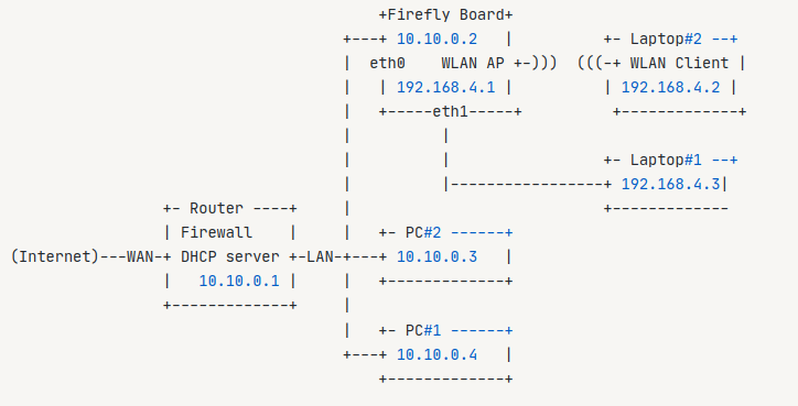
Suppose there is a local area network, the network segment is 10.10.0.0, and the mask is 255.255.255.0. Firefly’s development board, hereinafter referred to as Firefly Board, its network port obtains the dynamic IP address in the local area network through the router Router: 10.10.0.2.
Requirements: To configure the system as a soft route, the specific requirements are as follows:
(1) Firefly Board opens a wireless AP hotspot, and peripherals such as tablets and mobile phones access the network through the wireless AP hotspot to access the Internet.
(2) The wireless hotspot LAN enabled by Firefly Board is: 192.168.4.1
(3) If Firefly Board has multiple network ports, eth0 is required as the WAN port function, and the IP address is automatically obtained from the router, and eth1 is used as the LAN port function, which can assign The IP address of the 192.168.4.0/24 network segment.
The network topology is as follows:
6.5.2. Install the necessary software packages for managing AP hotspots
Install hostapd: hostapd can be used to simulate a soft AP, so it is necessary to achieve this function:
apt install hostapd
Allow hostapd to start on boot, so that the wireless AP hotspot will automatically open after restarting
systemctl unmask hostapd
systemctl enable hostapd
Install isc-dhcp-server: isc-dhcp-server is used to automatically assign IP addresses and DNS server addresses to devices connected to the wireless AP
apt install isc-dhcp-server
Allow isc-dhcp-server to start up
systemctl enable isc-dhcp-server
Install netfilter-persistent iptables-persistent: for saving firewall rules
apt install netfilter-persistent iptables-persistent
Install bridge-utils: for creating virtual bridges
apt install bridge-utils
6.5.3. Configure Netplan
The purpose is to create a bridge br0 with a bridge IP of 192.168.4.1. Allow the system eth0 network card to assign an IP address, prohibit the system from assigning an IP address to the eth1 network card, and bind the eth1 network card to the bridge br0.
Suppose the configuration file of netplan is: /etc/netplan/netplan.yaml, the content is as follows:
network:
        version: 2
        renderer: networkd
        ethernets:
                eth0:
                        dhcp4: yes
                eth1:
                        dhcp4: no

        bridges:
                br0:
                        dhcp4: no
                        addresses:
                                - 192.168.4.1/24
                        interfaces:
                                - eth1
Then run the following command to enable network configuration:
netplan apply
6.5.4. Configure hostapd
Create a hostapd.conf configuration file to set the name, password, channel and other properties of the wireless hotspot
vim /etc/hostapd.conf
Write the following in it:
country_code=CN
interface=wlan0
bridge=br0
ssid=Example-Wifi-Name
hw_mode=g
channel=11
macaddr_acl=0
auth_algs=1
ignore_broadcast_ssid=0
wpa=2
wpa_passphrase=12345678
wpa_key_mgmt=WPA-PSK
wpa_pairwise=TKIP
rsn_pairwise=CCMP
Important parameter description:
country_code: country code, China uses CNinterface: enable the wireless network card of the wireless AP hotspotbridge: bind to thebr0bridge, so that the wireless AP hotspot and the Ethernet port are in the same LANhw_mode: set the wireless modechannel: channelssid: wireless AP name, here setExample-Wifi-Namewpa_passphrase: Wireless AP password, here is set to12345678
For more information, the configuration of hostapd.conf is undoubtedly very complicated. The modes supported by hw_mode include a, g, channel channels are related to hw_mode, country_code, etc. Expand. If more automated and tight configuration of these wireless parameters is required, the OpenWRT softrouting system can be used instead of the Ubuntu system.
Next, you need to configure the global configuration file for hostapd
vim /etc/default/hostapd
Uncomment DAEMON_CONF and set its value to /etc/hostapd.conf created above
# Defaults for hostapd initscript
#
# See /usr/share/doc/hostapd/README.Debian for information about alternative
# methods of managing hostapd.
#
# Uncomment and set DAEMON_CONF to the absolute path of a hostapd configuration
# file and hostapd will be started during system boot. An example configuration
# file can be found at /usr/share/doc/hostapd/examples/hostapd.conf.gz
#
DAEMON_CONF="/etc/hostapd.conf"

# Additional daemon options to be appended to hostapd command:-
# -d show more debug messages (-dd for even more)
# -K include key data in debug messages
# -t include timestamps in some debug messages
#
# Note that -B (daemon mode) and -P (pidfile) options are automatically
# configured by the init.d script and must not be added to DAEMON_OPTS.
#
#DAEMON_OPTS=""
Restart the hostapd service
systemctl restart hostapd
At this point, you can already see through the mobile phone and other devices that there is a wireless AP hotspot open, named “Example-Wifi-Name”, but the device cannot be assigned an IP address after the connection, and the device will be disconnected immediately.
6.5.5. Configure isc-dhcp-server
isc-dhcp-server acts as a dhcp server, and automatically assigns IP addresses and DNS server addresses to devices connected to wireless AP nodes, such as Laptop1 and Laptop2 in the topology diagram.
Edit /etc/dhcp/dhcpd.conf,
vim /etc/dhcp/dhcpd.conf
Replace with the following:
# Specify the DNS address for the device, use "," to separate multiple DNS
option domain-name-servers 202.96.128.86,202.96.128.166,8.8.8.8,114.114.114.114;
default-lease-time 600;
max-lease-time 7200;
ddns-update-style none; ddns-updates off;

subnet 192.168.4.0 netmask 255.255.255.0 {
    range 192.168.4.2 192.168.4.200;
    option routers 192.168.4.1;
    option broadcast-address 192.168.4.255;
    option subnet-mask 255.255.255.0;
}
Important parameter description:
domain-name-servers: DNS server address list, assignDNSfor devices connected to the192.168.4.0/24network segmentsubnet 192.168.4.0 netmask 255.255.255.0: defines the subnet segment192.168.4.0/24range 192.168.4.2 192.168.4.200: assigned IP address rangeoption routers 192.168.4.1: default routeoption broadcast-address 192.168.4.255: broadcast addressoption subnet-mask 255.255.255.0: subnet mask
Restart isc-dhcp-server for the configuration to take effect:
systemctl restart isc-dhcp-server
6.5.6. Enable IP forwarding
After the above configuration, the device connected to eth1 and the device connected to the wireless AP hotspot can obtain the IP of the 192.168.4.0/24 network segment, and can ping 192.168.4.1, You can also view the DNS server address obtained by the device. But the device cannot access the internet yet.
Enable IP forwarding
sysctl -w net.ipv4.ip_forward=1
Set MASQUERADE (address spoofing). MASQUERADE and SNAT function roughly the same, MASQUERADE does not need to specify an explicit IP, it will dynamically change the source address of the packet to the IP address available on the specified network card.
iptables -t nat -A POSTROUTING -o eth0 -j MASQUERADE
Note that it is specified here as eth0, so that all IP packets of Firefly Board are forwarded to eth0, so that peripherals can access the Internet. It can also be specified as any network card that can access the external network, such as 4G network card usb0 , wwan0`, infer other things.
Now save the current firewall rules for IPv4 (including the rules above) and IPv6 to be loaded by the netfilter-persistent service at startup:
netfilter-persistent save
6.6. Configure IP address and routing using ip and netplan
6.6.1. Static IP address configuration
Multiple IP addresses can be configured on a network port interface at the same time. These IP addresses can belong to the same network or not belong to the same network. The first IP address configured is the primary IP address of the interface by default, and the IP address configured later is the secondary IP address of the interface.
6.6.1.1. Common IP configuration commands:
// Set the IP address of the interface
ip address add PREFIX [ broadcast ADDR ] dev IFNAME

// delete the IP address of the interface
ip address del PREFIX dev IFNAME

// View the IP address of the interface
ip address show/list [ dev IFNAME ]

// Clear all IP addresses of the interface
ip address flush [dev IFNAME]
6.6.1.2. Configuration example:
Configure primary IP: 192.168.2.2 for eth0 interface, secondary IP: 192.168.2.3
Temporary configuration
ip address add 192.168.2.2/24 dev eth0
ip address add 192.168.2.3/24 dev eth0
Persistent configuration: use Netplan
network:
  version: 2
  renderer: networkd
  ethernets:
    eth0:
      dhcp4: no
      addresses:
          - 192.168.2.2/24
          - 192.168.2.3/24
6.6.2. Dynamic IP address configuration
Operating systems generally automatically assign IP addresses to network interfaces. For the buildroot system, the dhcpcd service will send a dhcp request to the DHCP server (here, the DHCP server is most likely your route) to request the IP address of the interface. In Ubuntu systems, this process is done by NetworkManager.
Temporary configuration
udhcpc -i eth0/eth1

# or
dhclient eth0/eth1
Persistent configuration: use netplan
network:
  version: 2
  renderer: networkd
  ethernets:
    eth0:
      dhcp4: yes
6.6.3. Static routing configuration
The opposite of static routing is dynamic routing. Dynamic routing includes OSPF and RIP. These two protocols only exist in routers. For non-router devices, if a destination network segment cannot be reached directly, a static route needs to be configured to tell the device the IP address of the destination network segment, outgoing interface, and next hop.
6.6.3.1. Common configuration commands:
# View routing table
route -n
# or
netstat -rn

# Add IP static route
ip route add PREFIX via ADDRESS dev IFNAME [ metric METRIC ]

# delete IP static route
ip route del PREFIX via ADDRESS dev IFNAME [metric METRIC]

# clear IP route
ip route flush dev IFNAME
6.6.3.2. Configuration example:
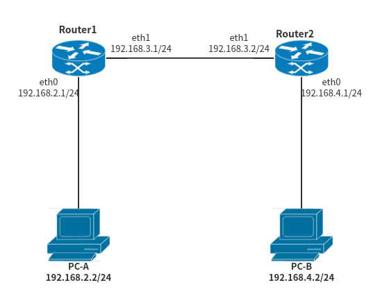
Assuming that there is such a network topology, Router1 and Router2 in the figure are our development board devices, and the running system is the Ubuntu operating system. In this network, for Router1, the network segment 192.168.2.0/24 and the network segment 192.168.3.0/24 belong to the directly connected network segment for Router1, which means that for PC-A, the access network segment 192.168.2.0/24 There is no problem with the network segment 192.168.3.0/24, but the network segment 192.168.4.0/24 cannot be accessed. This is because the network segment 192.168.4.0/24 is invisible to Router1. A static route needs to be configured on Router1. This static route indicates that to the destination network segment 192.168.4.0/24, the next IP address is 192.168.3.2/24, and the outgoing interface is eth1 of Router1. Similarly, for Router2, the network segment 192.168.3.0/24 and the network segment 192.168.4.0/24 belong to the directly connected network segment, and PC-B also cannot access the network segment 192.168.2.0/24. It is necessary to configure a static network segment on Router2. The route indicates that to the destination network 192.168.2.0/24, the next hop IP address is 192.168.3.1/24, and the outgoing interface is eth1 of Router2.
Temporary configuration
For Router1:
# Enable IP forwarding
echo 1 > /proc/sys/net/ipv4/ip_forward

# Set the IP address of eth0, eth1
ip addr add 192.168.2.1/24 dev eth0
ip addr add 192.168.3.1/24 dev eth1

# configure static routes
ip route add 192.168.4.0/24 via 192.168.3.2 dev eth1
For Router2:
# Enable IP forwarding
echo 1 > /proc/sys/net/ipv4/ip_forward

# Set the IP address of eth0, eth1
ip addr add 192.168.4.1/24 dev eth0
ip addr add 192.168.3.2/24 dev eth1

# configure static routes
ip route add 192.168.2.0/24 via 192.168.3.1 dev eth1
persistent configuration
For Router1 and Router2, execute the following commands to permanently enable IP forwarding
sysctl -w net.ipv4.ip_forward=1
For Router1, configure Netplan
network:
        version: 2
        renderer: networkd
        ethernets:
                eth0:
                        addresses:
                                - 192.168.2.1/24
                eth1:
                        addresses:
                                - 192.168.3.1/24
                        routes:
                                - to: 192.168.4.0/24
                                  via: 192.168.3.2
For Router2, configure Netplan
network:
        version: 2
        renderer: networkd
        ethernets:
                eth0:
                        addresses:
                                - 192.168.4.1/24
                eth1:
                        addresses:
                                - 192.168.3.2/24
                        routes:
                                - to: 192.168.2.0/24
                                  via: 192.168.3.1
6.6.4. Default routing configuration
Temporary configuration
The operating system automatically assigns a default route to an interface that obtains an IP address dynamically through the DCHP service. For static IP address configuration, a default route needs to be set manually for it.
Or take the above example to explain, assuming that PC-A is a Linux operating system, we need to configure the following:
# Configure the network card IP, assuming its network card is eth0
ip addr add 192.168.2.2/24 dev eth0

# configure default route
ip route add 0.0.0.0/0 via 192.168.2.1 dev eth0
Persistent configuration: use Netplan
network:
        version: 2
        renderer: networkd
        ethernets:
                eth0:
                        addresses:
                                - 192.168.2.2/24
                        routes:
                                - to: 0.0.0.0/0
                                  via: 192.168.2.1
6.6.5. Adjust default routing order
In the development board with dual network ports, if the IP addresses of the two network ports are automatically obtained through DHCP, the operating system will generate two default routes, each network port has a default route, and the network port of the network cable is inserted first. Or get the IP network port first, and you will get a higher routing priority. As shown below, there are two default routes, and the default route of the eth0 network card has a higher priority than eth1. This means that when the development board communicates by default, it uses the eth0 network card.
root@firefly:~# ip route list
default via 168.168.0.1 dev eth0 proto dhcp metric 100
default via 168.168.0.1 dev eth1 proto dhcp metric 101
168.168.0.0/16 dev eth0 proto kernel scope link src 168.168.110.72 metric 100
168.168.0.0/16 dev eth1 proto kernel scope link src 168.168.110.111 metric 101
6.6.5.1. Configuration example:
Suppose there is a situation, the network segment of Wireless Router1 is 192.168.3.0/24, and the network segment of Wireless Router2 is 192.168.2.0/24. At this time, for Firefly Board, both eth0 and eth1 obtain IP addresses dynamically. If eth0 The default route has a higher priority than the default route of eth1. The default route of eth0 will be used for communication. Since the network where eth0 is located has no external network connection, the Firefly Board cannot access the Internet. At this time, you can modify the priority of the default route. to solve.
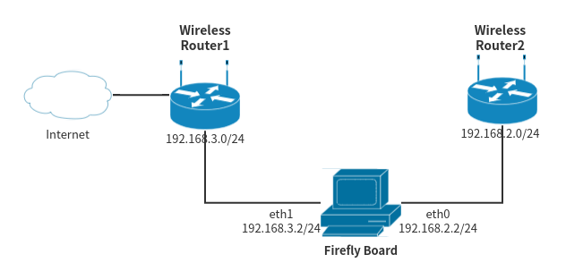
The Netplan configuration is as follows. The metric value of eth1 is smaller than that of eth0. The smaller the value, the higher the priority.
network:
        version: 2
        ethernets:
                eth0:
                        dhcp4: yes
                        dhcp4-overrides:
                                route-metric: 200
                eth1:
                        dhcp4: yes
                        dhcp4-overrides:
                                route-metric: 100
6.7. iptables NAT configuration
The network translation technology is also called NAT (Network Address Translation) technology. Its basic function is to realize the translation between private IP addresses and public IP addresses.
In Linux systems, NAT can be refined into SNAT (Source Network Address Translation) and DNAT (Destination network address translation). SNAT, also known as source address translation technology, is used to change the source IP in the IP data packet to the IP address of the router or firewall before the IP data packet reaches the external network when the private network host initiates network communication with the external network host. , so that the external network host cannot know the private network IP address of the internal network host. DNAT, also known as target address translation technology, is used when external network hosts need to access network services provided by internal network hosts, such as http, when IP packets reach routers or firewalls, they will change the target IP in the IP packets to The IP of the private network host that provides network services.
6.7.1. Common commands
We can implement SNAT and DNAT by configuring the nat table of iptables
# View nat rules
iptables -t nat -vnL

# clear nat rules
iptables -t nat -F

# Add a SNAT rule to map the IP of the internal network to the IP of the external network
iptables -t nat -A POSTROUTING -s LocalIP -j SNAT --to-source ExtIP

# Add a DNAT rule to map the IP and port of the external network to the IP and port of the internal network
iptables -t nat -A PREROUTING -d ExtIP -p tcp|udp --dport PORT -j DNAT --to-destination LocalIP[:PORT]
iptables also supports MASQUERADE (address spoofing), its function is basically the same as SNAT, and it can also play the role of source address translation. In a special case, if the IP address of the external network is not a fixed and long-term valid IP address, such as an IP address dynamically obtained by dialing through pppoe, MASQUERADE can be used to implement source address translation. MASQUERADE does not need to specify an explicit IP, and will dynamically change the source address of the packet to the IP address available on the specified network card.
# Add a MASQUERADE rule to map the IP of the internal network to the IP of the external network card (the internal IP can be omitted here, and by default all the IPs of the internal network are mapped to the IP of the external network card)
iptables -t nat -A POSTROUTING [-s LocalIP] -o IFNAME -j MASQUERADE
6.7.2. Configuration example
Assuming such a network topology exists, use 10.1.0.0/16 to simulate a public network, and use 192.168.1.0/24 to simulate a private network. The machines in the figure are all machines that are simulated with a Linux host.
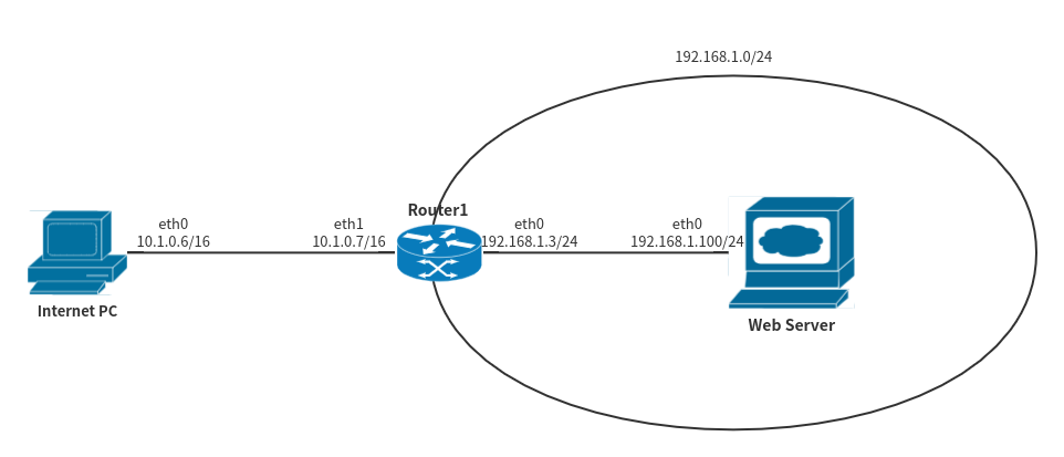
For Router1, it is a router connected to the internal and external networks, and its netplan configuration is as follows:
network:
        version: 2
        renderer: networkd
        ethernets:
                eth0:
                        addresses:
                                - 192.168.1.3/24
                eth1:
                        addresses:
                                - 10.1.0.7/16
At the same time, for Router1, you need to enable the IP forwarding function:
echo 1 > /proc/sys/net/ipv4/ip_forward
For the Internet PC, it is a personal host on the external network, and its netplan configuration is as follows:
network:
        version: 2
        renderer: networkd
        ethernets:
                eth0:
                        addresses:
                                - 10.1.0.6/16
For Web Server, it is a private network server that provides http services. Its netplan configuration is as follows:
network:
        version: 2
        renderer: networkd
        ethernets:
                eth0:
                        addresses:
                                - 192.168.1.100/24
                        routes:
                                - to: 0.0.0.0/0
                                  via: 192.168.1.3/24
6.7.3. SNAT
Requirement: In the current network structure, the internal network host cannot access the external network.
Add a SNAT rule, modify the IP data packets sent by the internal network host to the external network, and change the source IP address to the IP of the 192.168.1.0/24 network segment to 10.1.0.7
iptables -t nat -A POSTROUTING -s 192.168.1.0/24 -j SNAT --to-source 10.1.0.7
Authentication method:
Web Server on the internal network, ping the Internet PC on the external network
~ ping -c 4 10.1.0.6 ok
PING 10.1.0.6 (10.1.0.6) 56(84) bytes of data.
64 bytes from 10.1.0.6: icmp_seq=1 ttl=63 time=2.15 ms
64 bytes from 10.1.0.6: icmp_seq=2 ttl=63 time=2.12 ms
64 bytes from 10.1.0.6: icmp_seq=3 ttl=63 time=1.99 ms
64 bytes from 10.1.0.6: icmp_seq=4 ttl=63 time=2.14 ms

--- 10.1.0.6 ping statistics ---
4 packets transmitted, 4 received, 0% packet loss, time 7ms
rtt min/avg/max/mdev = 1.989/2.098/2.147/0.063 ms
Web Server on the intranet, capture packets
root@firefly:/# tcpdump -i eth1 -nn icmp
tcpdump: verbose output suppressed, use -v or -vv for full protocol decode
listening on eth1, link-type EN10MB (Ethernet), capture size 262144 bytes
03:33:37.503348 IP 10.1.0.7 > 10.1.0.6: ICMP echo request, id 53287, seq 1, length 64
03:33:37.503603 IP 10.1.0.6 > 10.1.0.7: ICMP echo reply, id 53287, seq 1, length 64
03:33:38.503348 IP 10.1.0.7 > 10.1.0.6: ICMP echo request, id 53287, seq 2, length 64
03:33:38.503560 IP 10.1.0.6 > 10.1.0.7: ICMP echo reply, id 53287, seq 2, length 64
03:33:39.504601 IP 10.1.0.7 > 10.1.0.6: ICMP echo request, id 53287, seq 3, length 64
03:33:39.504812 IP 10.1.0.6 > 10.1.0.7: ICMP echo reply, id 53287, seq 3, length 64
03:33:40.505347 IP 10.1.0.7 > 10.1.0.6: ICMP echo request, id 53287, seq 4, length 64
03:33:40.505557 IP 10.1.0.6 > 10.1.0.7: ICMP echo reply, id 53287, seq 4, length 64
6.7.4. DNAT
Requirements: The intranet Web Server provides http services, and the external network host wants to access the web pages of the intranet.
Add a DNAT rule, modify the IP data packets sent from the external network to the internal network, and change the destination IP address and port number to the IP and port number of the internal network web server.
iptables -t nat -A PREROUTING -d 10.1.0.7 -p tcp --dport 8000 -j DNAT --to-destination 192.168.1.100:8000
Authentication method:
Access the web services of the intranet Web Server from the Internet PC on the external network
root@firefly:/# wget http://10.1.0.7:8000/index.html
--2021-02-19 03:31:12-- http://10.1.0.7:8000/index.html
Connecting to 10.1.0.7:8000... connected.
HTTP request sent, awaiting response... 200 OK
Length: 41323 (40K) [text/html]
Saving to: ‘index.html’

index.html 100%[==================>] 40.35K --.-KB/s in 0.001s

2021-02-19 03:31:12 (29.8 MB/s) - ‘index.html’ saved [41323/41323]
6.7.5. MASQUERADE
Requirements: If Router1 is connected to the internal and external network, it has only one external network card, which is eth1, and the IP address is dynamically obtained.
Solution: Add a MASQUERADE rule to send IP packets from the intranet 192.168.1.0/24 to the external network, and modify the source IP address to the IP address of the eth1 network card.
iptables -t nat -A POSTROUTING -s 192.168.1.0/24 -o eth1 -j MASQUERADE
6.8. iptables filter configuration
The filter table (filtering rule table) of iptables is used to control whether data packets are allowed to enter, exit and forward. The links that the filter table can control are INPUT, FORWARD, and OUTPUT. Commonly used actions are ACCEPT, DROP, REJECT.
6.8.1. General commands
# Clear the filter table
iptables -t filter -F

# show filter table
iptables -t filter -nvL
6.8.2. ACCEPT: allow packets to pass through
Configuration example: By default, ssh uses port 22 for tcp communication. If you want to enable remote access, you need to enable tcp connection on port 22.
iptables -A INPUT -t filter -p tcp --dport 22 -j ACCEPT
Enable ssh access and allow access from the 192.168.0.0/24 network segment
iptables -A INPUT -t filter -p tcp -s 192.168.0.0/24 --dport 22 -j ACCEPT
Enable ssh access to allow received packets from the eth0 network card
iptables -A INPUT -t filter -p tcp -i eth0 --dport 22 -j ACCEPT
Enable ssh access to allow the host with the MAC address of 00:50:8D:FD:E6:32 in the 192.168.0.0/24 network segment to access
iptables -A INPUT -t filter -p tcp -s 192.168.0.0/24 --dport 22 -m mac --mac-source 00:50:8D:FD:E6:32 -j ACCEPT
6.8.3. REJECT: Deny the packet to pass
The common option for REJECT action is –reject-with (using the –reject-with option, you can set a prompt message, when the other party is rejected, it will prompt the other party why it was rejected)
For the ICMP protocol, the available values are as follows, if not provided, it defaults to icmp-port-unreachable
icmp-net-unreachable
icmp-host-unreachable
icmp-port-unreachable,
icmp-proto-unreachable
icmp-net-prohibited
icmp-host-pro-hibited
icmp-admin-prohibited
Configuration example: reject external ping and prompt “Destination Host Unreachable”
iptables -A INPUT -t filter -p icmp -j REJECT --reject-with icmp-host-unreachable
6.8.4. DROP: drop packets
Configuration example: directly discarding external ping packets
iptables -A INPUT -t filter -p icmp -j DROP
7. Qt support
7.1. Qt environment support
If your Firefly device is using Ubuntu 22.04, then you can install Qt with apt
# Install basic env
apt update
apt install -y qtcreator qtbase5-dev

# Install additional plugins and dev pack
apt install -y libqt5multimedia5 qtmultimedia5-dev libqt5quick5 qtdeclarative5-dev
Then you can develop on deivce.
Ubuntu 18.04 Or Ubuntu 20.04 need to use PC to cross-compile, please read the following chapter:
7.2. Qt cross compilation environment support
Firefly released two Qt cross-compilation tool chains, suitable for the following environments:
Qt: 5.12.2
Host: x86-64 / Ubuntu 18.04
Target: Firefly RK3568 RK3566 RK3399 RK3328 PX30 / Ubuntu 18.04 Minimal&Desktop
and
Qt: 5.15
Host: x86-64 / Ubuntu 20.04
Target: Firefly RK3588 RK3568 RK3566 / Ubuntu 20.04 Desktop
The tool chain fully supports wenEngine and backends such as EGLFS LinuxFB XCB.
download link
Link: https://drive.google.com/drive/folders/1QF9T-KY-LyQyJy1e-9yrqmryz-avQ8Qj?usp=sharing
Deployment
See Qt5.1x.x_Release.md in tool-chain package for details
Note that the names of all paths in the document cannot be changed, otherwise it will cause compilation or running errors.
Compile
On the host side, enter the Qt project directory, qmake && make.
Run
Demos are provided in the tool chain. After the deployment is completed, the user can build the demo on the host side and run the demo on the tartget side to test whether the deployment is successful.
After deciding which backend to use, you can modify the /etc/profile.d/target_qtEnv.sh in target, uncomment the environment variables of corresponding backend to keep it in effect.
# For example, using XCB, then uncomment the XCB part

#XCB
export QT_QPA_PLATFORM=XCB
export QT_QPA_EGLFS_INTEGRATION=XCB_EGL
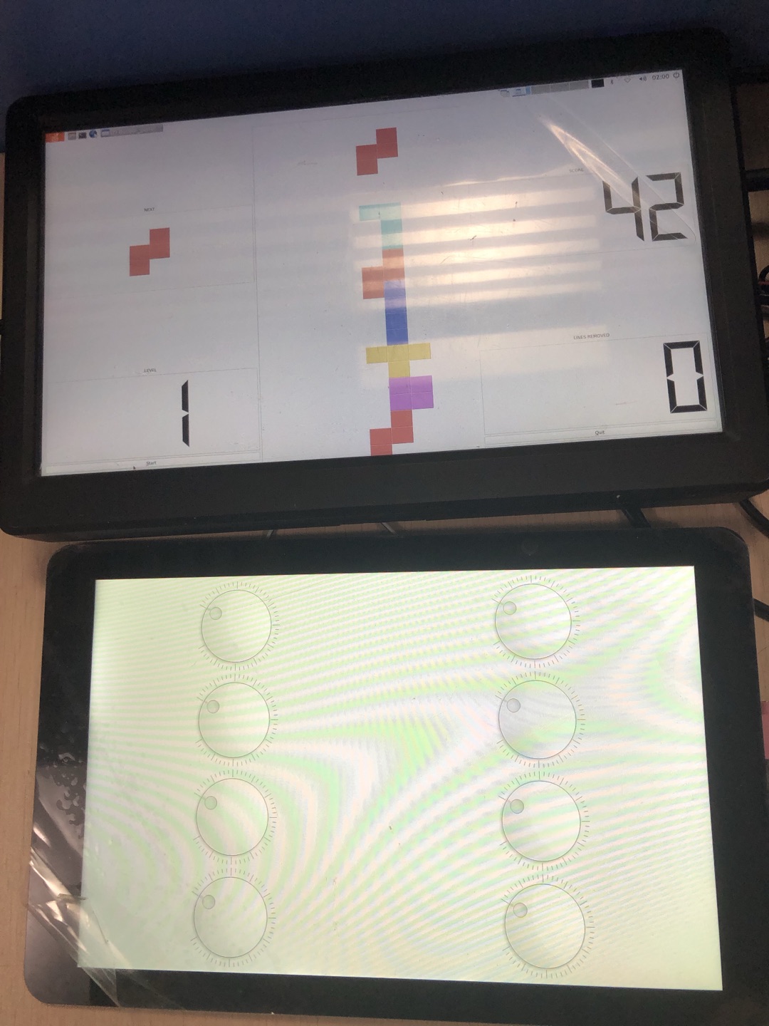
7.3. Qt dual screen different display
The object is to demonstrate the use of Qt demo application Ubuntu system implementation and operation of dual-screen display.
(1)Into the desktop environment
export XAUTHORITY=/home/firefly/.Xauthority
export DISPLAY=:0
(2)Set environment variables
export QT_QPA_PLATFORM=xcb
export QT_QPA_EGLFS_INTEGRATION=XCB_EGL
(3)Run the demo
./firefly_arm64_qt5.12.2_18.04/demo/double_panel_demo
(4)Demo code directory
firefly_arm64_qt5.12.2_18.04/example/double_panel_demo
(5)Code compilation
cd example
qmake
make
(6)Add your own Qt project
Add your own Qt project in the
exampledirectory.Edit the
gui.profile in theexampledirectory.Assuming that the project directory is named
double_panel_demo, addSUBDIRS += double_panel_demoto thegui.profile.qmake && make.
(7)Running effect
7.4. Qt Creator
If your target platform OS is Ubuntu 22.04, then you can skip this chapter. Just use qtcreator on device and no special settings needed.
Other OS needs cross-compiling env, please read the following contents:
Here is the manual for Qt Creator on host PC, Please install and configure firefly Qt environment first.
7.4.1. Install
Go Qt download page, choose one version like qt-creator-opensource-linux-x86_64-x.x.x.run, download and then execute ./xxx.run to install. Note that the file has to be executable.
7.4.2. Configuration
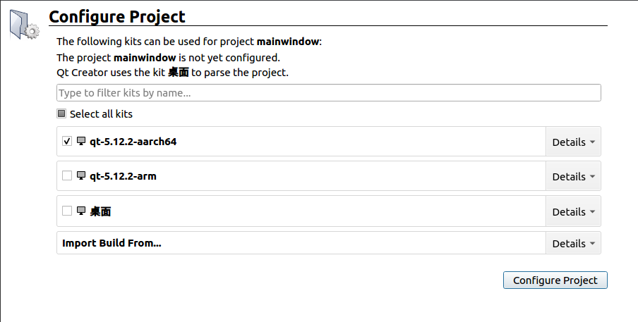
Here we use firefly-qt-5.12.2-aarch64 as example, the target platform uses Buildroot system:
The configuration varies slightly depending on the target system, so please read the text carefully, pictures for reference only, do not just copy configuration in the picture
Launch Qt Creator, open Tools -> Options, find Kits page.
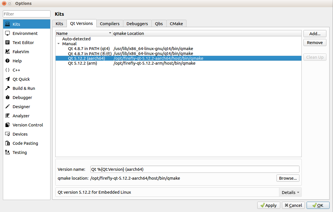
Select Qt Versions
Click
addbutton on the right, select qmake in the Qt environment installation location.qmake:
/opt/firefly-qt-5.12.2-aarch64/host/bin/qmake
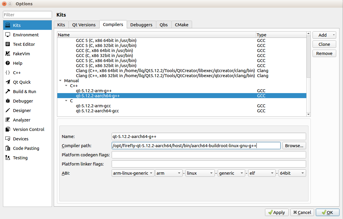
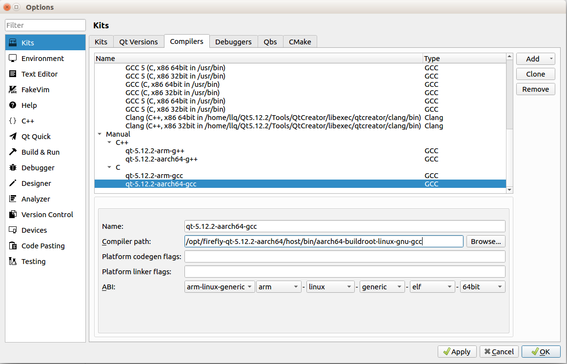
Select Compilers
Click
addbutton on the right to add gcc and g++ compilers.If crossbuild-essential-arm64 is installed on host PC, then the compilers are under
/usr/bin/.If using 3rd-party compilers, just find compilers’ installation location.
If the target uses Buildroot, use the compilers in the Buildroot Qt environment package.
g++:
/opt/firefly-qt-5.12.2-aarch64/host/bin/aarch64-buildroot-linux-gnu-g++gcc:
/opt/firefly-qt-5.12.2-aarch64/host/bin/aarch64-buildroot-linux-gnu-gcc
For easily debug, configure gdb and devices for online debugging:
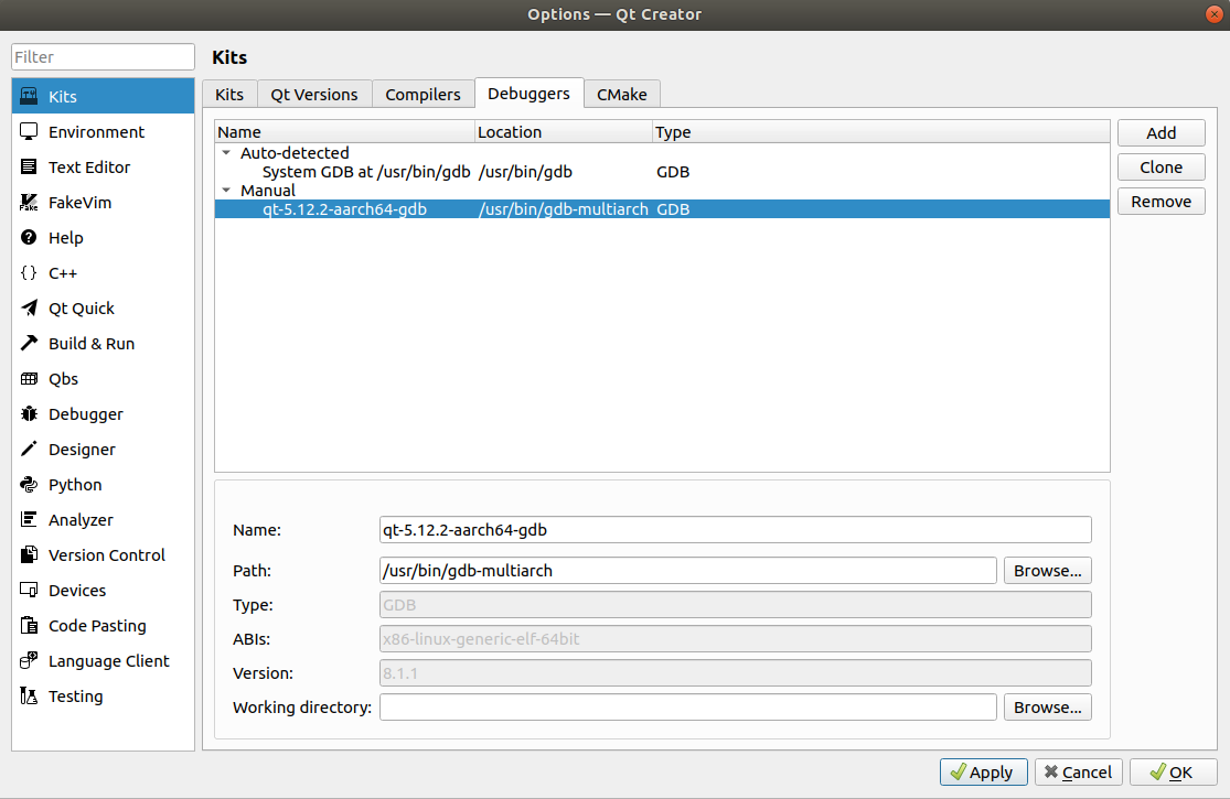
Select Debuggers
First install gdb-multiarch on host:
apt install -y gdb-multiarchCheck if /usr/bin/gdbserver exist on target. If not, install it:
apt install -y gdbserver(Buildroot comes with gdbserver, no need to install)Back to host Qt Creator, click
addto add gdbSelect gdb-multiarch :
/usr/bin/gdb-multiarch
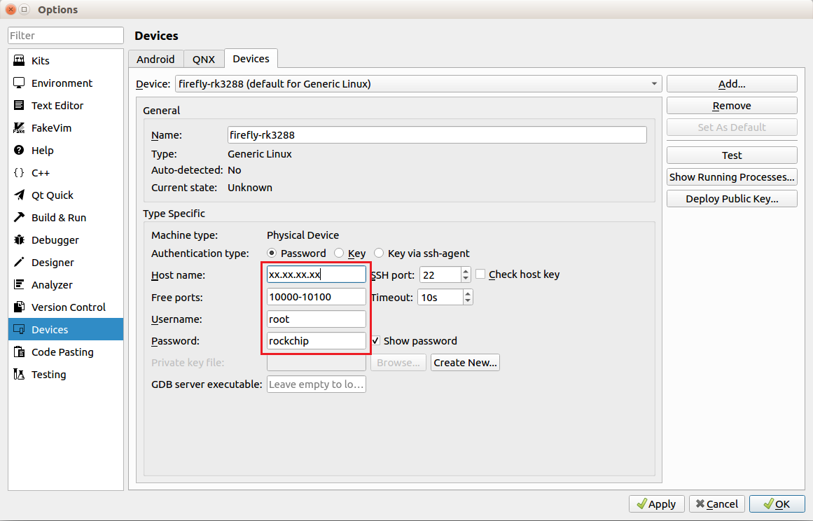
Configure Devices
Set the IP, username (root) and password (firefly). You can use static IP on target.
Set the GDB server:
/usr/bin/gdbserver
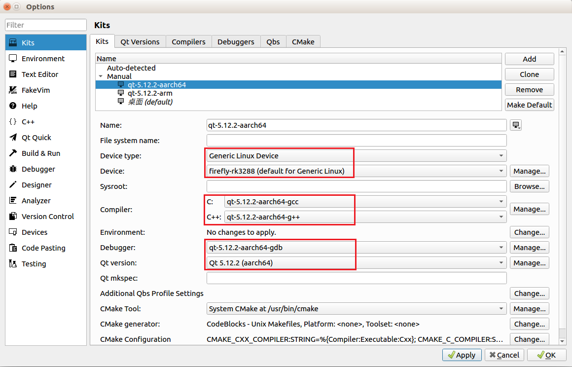
Configure Kits
Add previous settings into Kits.
If target uses Ubuntu, you need to set sysroot.
7.4.3. Compile and Run
Click Welcome -> Open Project to open a demo project, choose the Kits:
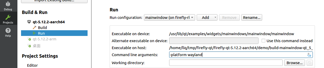
Then click Projects -> Run to set platform parameters -platform wayland:
Ubuntu target need to use -platform xcb, or linuxfb, eglfs as you need.
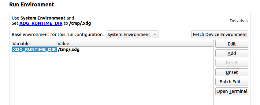
Configure envionment variables export XDG_RUNTIME_DIR=/tmp/.xdg:
RK356X Buildroot needs to use /var/run, not /tmp/.xdg
Ubuntu target needs to set different variables according to platform selected above, read the README file in Qt environment package.
If the target Qt environment (mentioned at the beginning) is already prepared and demo ran successfully, then you can click Fetch Device Environment in this step.
Compile and run:
Click Build to compile Qt program; Run or Debug for running and debugging.
To restart the program, remember to click Stop first.
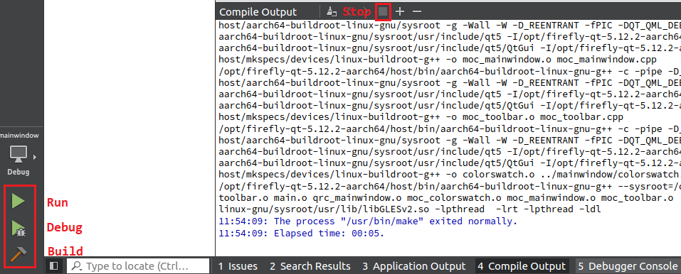
The output directory has the same location as demo directory.
8. Docker support
Firefly normal firmware generally does not meet Docker operation requirements. If there is a need, you can use SDK to enable related kernel configs and rebuild the kernel to support Docker.
(RK356X v1.2.4a and later version, RK3399/RK3588 support Docker by default, you can skip straight to the installation step)
The following case is based on Firefly Ubuntu 20.04, and the kernel configuration part is generic!
8.1. Check Kernel Configuration
First use script to see which configuration is needed by Docker but missing in current kernel. You can get the check script from GitHub.
After get the script, begin to check:
#Copy the script to SDK/kernel/
cp check-config.sh PathToSDK/kernel/
cd PathToSDK/kernel
chmod +x check-config.sh

#Get current kernel configuration
make ARCH=arm64 firefly_linux_defconfig

#Check
./check-config.sh .config
The result looks like this, mainly two parts:
Generally Necessary:
- cgroup hierarchy: properly mounted [/sys/fs/cgroup]
- apparmor: enabled and tools installed
- CONFIG_NAMESPACES: enabled
- CONFIG_NET_NS: enabled
- CONFIG_PID_NS: enabled
- CONFIG_IPC_NS: enabled
- CONFIG_UTS_NS: enabled
- CONFIG_CGROUPS: enabled
......

Optional Features:
- CONFIG_USER_NS: enabled
- CONFIG_SECCOMP: enabled
- CONFIG_SECCOMP_FILTER: enabled
- CONFIG_CGROUP_PIDS: enabled
- CONFIG_MEMCG_SWAP: enabled
......
Generally Necessary: All features in this part need to be enabled in kernel.
Optional Features: Enable them as you needed.
8.2. Enable Needed Features
From the result you can find out which features are need to be enabled, then use make ARCH=arm64 menuconfig to enter config menu, search and enable them. Please read the instructions in the config menu, if some features can’t be selected, check the dependency.
Enabled all the necessary features and some optional features, remember to save:
make ARCH=arm64 savedefconfig
mv defconfig arch/arm64/configs/firefly_linux_defconfig
Compile the kernel:
#Back to SDK dir
cd ..
#Compile
./build.sh kernel
8.3. Install Docker
After burning new kernel, install Docker on device (This method works on PC as well)
Step1:Quick install
# Here only introduces the quick-install using script
apt-get update
wget -qO- https://get.docker.com/ | sh
You should see the Docker version information after the installation is successful.
Step2:Check docker root dir (This step is only for PC docker installing)
If you are installing docker in Firefly device, please skip this step.
# execute
docker info | grep -i dir
# result
 Docker Root Dir: /var/lib/docker
The result shows docker root dir, this location may be different on different PC.
Images and containers need large disk space, if the default location does not have enough space, you need to change the default location to one with sufficient space.
Emphasize again:This step is only for PC, in Firefly device, change this dir will cause docker error, please go to next step.
# stop docker service first
sudo systemctl stop docker

# modify /lib/systemd/system/docker.service
sudo vim /lib/systemd/system/docker.service

# add your destination dir at the end of ExecStart line: --graph /home/firefly/docker/data
ExecStart=/usr/bin/dockerd -H fd:// --containerd=/run/containerd/containerd.sock --graph /home/firefly/docker/data

# start docker service
sudo systemctl daemon-reload
sudo systemctl start docker

# check if the location is updated
docker info | grep -i dir
 Docker Root Dir: /home/firefly/docker/data
Step3:add your user to docker group
sudo usermod -a -G docker firefly
# reboot
sudo reboot
Step4:After reboot, run demo to test docker:
firefly@firefly:~# docker run hello-world
Unable to find image 'hello-world:latest' locally
latest: Pulling from library/hello-world
93288797bd35: Pull complete
Digest: sha256:cc15c5b292d8525effc0f89cb299f1804f3a725c8d05e158653a563f15e4f685
Status: Downloaded newer image for hello-world:latest

Hello from Docker!
This message shows that your installation appears to be working correctly.

To generate this message, Docker took the following steps:
 1. The Docker client contacted the Docker daemon.
 2. The Docker daemon pulled the "hello-world" image from the Docker Hub.
    (arm64v8)
 3. The Docker daemon created a new container from that image which runs the
    executable that produces the output you are currently reading.
 4. The Docker daemon streamed that output to the Docker client, which sent it
    to your terminal.

To try something more ambitious, you can run an Ubuntu container with:
 $ docker run -it ubuntu bash

Share images, automate workflows, and more with a free Docker ID:
 https://hub.docker.com/

For more examples and ideas, visit:
 https://docs.docker.com/get-started/
9. ROS support
9.1. Install the ROS
Follow the official installation tutorial to install ROS. Official Installation Tutorial
9.2. Install libglx
Rviz and Gazebo are written based on GLX. Our system only supports EGL at present, so they cannot use GPU acceleration, and GLX library needs to be installed to run properly.
apt install -y libgl1-mesa-glx libgl1-mesa-dri libglx-mesa0
reboot
9.3. Update libqt5opengl5-dev
If RVIz does not run, RQT displays errors such as QOpenGLTimeMonitor. You need to update libqt5OpengL5-dev. Do the following to try running programs like RQT, RVIz, and Gazebo.
sed -i 's/.*wiki.t-firefly.com.*/\#&/' /etc/apt/sources.list
apt reinstall libqt5gui5
apt reinstall libqt5opengl5-dev
sed -i '/.*wiki.t-firefly.com.*/s/^#//' /etc/apt/sources.list
9.4. Run Rviz, RQT and Gazebo under Wayland
GLX-based programs run in Wayland and need to use XWayland. Use QT_QPA_PLATFORM=xcb to force Qt applications to use X11.
QT_QPA_PLATFORM=xcb rviz
QT_QPA_PLATFORM=xcb rqt
QT_QPA_PLATFORM=xcb gazebo
# You can also set the environment to bashrc to run programs like RVIz directly.
echo "export QT_QPA_PLATFORM=xcb" >> /~/.bashrc
9.5. ROS Tutorials
10. Graphics support
For the Rockchip platform, there are mainly the following graphics architectures to choose from:
Qt + Wayland
Qt + EGLFS
EGL program + X11
Wayland
None
Multi-window functional requirements, choose:
X11
Wayland
The functional requirements of the desktop, choose:
X11
4K video playback + full screen:
Qt + Wayland
Qt + EGLFS
X11
Wayland
4K video playback + multiple windows:
X11
Qt + Wayland
Wayland
If you don’t understand the technology of graphics architecture, you can continue reading.
10.1. X11
X11 is the 11th version of the X display protocol.
The X protocol has been used for 30 years. The Client/Server structure of the X protocol was originally designed to send rendering requests to the X server by the device (Client side) when the hardware performance was too weak before (the X server was previously running on another Independent hardware) rendering display.
However, with the continuous improvement of modern hardware performance, Client and Server can be run on the same hardware system at the same time, but the consequence of using this remote communication structure on the local machine is the loss of performance. At present, there are branches in the official Debian branch. Wayland was developed to replace X11, but Wayland is currently not compatible with existing software, so it has not been officially replaced.
![]()
Reference materials:
https://en.wikipedia.org/wiki/X.Org_Server
https://www.comptechdoc.org/os/linux/howlinuxworks/linux_hlxwindows.html
https://dri.freedesktop.org/wiki/DDX/
https://www.freedesktop.org/wiki/Software/Glamor/
https://en.wikipedia.org/wiki/X.Org_Server
10.2. Qt + EGLFS
Qt + EGLFS is a GUI system implemented by Qt itself. It does not support multiple windows, but window composite is therefore missing.
The method of Qt + EGLFS and dri2 is similar. The difference is that the font buffer of Qt + EGLFS is directly sent to the DRM display after using gpu composite by itself, while the X is sent to the Window manager for composite, so EGLFS is efficient Advantageous.
![]()
10.3. Qt + Wayland
In Wayland, Weston is the specific implementation of the Wayland display protocol, and its corresponding relationship is just like the relationship between Xorg (X server) and X.
The only disadvantage of the current comparison between Wayland and X is the compatibility, so most of the current mainstream system versions still use X.
Weston no longer uses the X’s Client/Server structure, but directly receives the kernel events from the synthesizer and passes them to the client, which is directly rendered by the client. Only the areas that need to be updated are sent to the synthesizer, and the synthesizer notifies the kernel. Arrange for page turning.
It should be noted that since Ubuntu/Debian already has X11, the SDK adds Weston support in Buildroot by default. In fact, if Ubuntu/Debian needs to install Weston, it can also be built on the Minimal version. (Firefly Ubuntu 20.04 will come with Wayland and X by default, and you can switch freely.)
![]()
It is recommended to use Buildroot/Yocto for Wayland development. In terms of efficiency, Wayland is better than X11, mainly due to compatibility issues.
If you don’t need a desktop, but also need multiple windows, you can try Wayland.
10.4. None
In addition to X11 and Wayland, there is also None, which is also more exposed on embedded systems. For example, MiniGUI and SDL are the same.
If you want to support DRM and opengl, you can only choose Qt.
MiniGUI is a lightweight embedded graphics library. The requirements for system resources fully take into account the hardware conditions of embedded devices. For example, the minimum space occupied by the MiniGUI library can be cut to about 500K.
In view of the characteristics of the Buildroot system adapting to devices with tight hardware resources, MiniGUI with Buildroot is a perfect fit.
Reference materials:
https://wayland.freedesktop.org/architecture.html
https://en.wikipedia.org/wiki/Wayland