3. Display
RK3576 has three video output ports, each video output port is bound to a fixed display controller, such as Port0 can be used to connect with display controllers such as DP0, DP1, HDMI/eDP0 and HDMI/eDP1, other Portx and so on.
Each Portx has its own maximum resolution:
Port0 can output up to 4K@120Hz
Port1 can output up to 2560x1600@60Hz
Port2 can output up to 1920x1080@60Hz
In software, if the HDMI0 display controller is connected to Port0, and the hardware phy supports HDMI2.1, then HDMI0 supports 4K@120Hz output.
If each Portx is assigned a separate display controller, it can support three-screen simultaneous display (different display) at the same time.
3.1. ROC-RK3576-PC Displays the configuration of the interface
ROC-RK3576-PC There are three display output interfaces, namely HDMI, Display Port and MIPI DSI, which can achieve multi-screen simultaneous display/exclusive display. The interface diagram is as follows:
HDMI/ Display Port/ MIPI DSI

The following is a basic introduction to the configuration and use of each display output interface. For details, please refer to the file:
kernel/arch/arm64/boot/dts/rockchip/rk3576-firefly-roc-rk3576-pc.dtsikernel/arch/arm64/boot/dts/rockchip/rk3576-firefly-roc-rk3576-pc-mipi101-M101014-BE45-A1.dts
3.1.1. HDMI
ROC-RK3576-PC There are one HDMI display output interfaces on the hardware:
HDMI supports HDMI2.1 protocol, resolution can support up to 4k@120Hz
3.1.1.1. Software configuration
The following takes the configuration of HDMI0 as an example.
//enable hdmi0
&hdmi {
	status = "okay";
	enable-gpios = <&gpio2 RK_PB0 GPIO_ACTIVE_HIGH>;
	rockchip,sda-falling-delay-ns = <360>;
};

//connect hdmi0 with Port0
&hdmi_in_vp0 {
	status = "okay";
};

//enable hdmi0 audio output
&hdmi_sound {
        status = "okay";
};

//enable hdmi0's phy
&hdptxphy_hdmi {
	status = "okay";
};

//enable hdmi0 logo of startup
&route_hdmi {
	status = "okay";
	connect = <&vp0_out_hdmi>;
};
3.1.2. Display Port
ROC-RK3576-PC has a Display Port display output interface, supports DP TX 1.4a protocol, and resolution can support up to 4k@120Hz.
3.1.2.1. Software configuration
Display Port is represented as dp0 on the system status tree, add:
// enable dp0 audio output
&spdif_tx3 {
	status = "okay";
};

&dp0_sound{
        status = "okay";
};

//enable dp0
&dp {
	status = "okay";
};

&dp0 {
        status = "okay";
};

//connect dp0 with port2
&dp0_in_vp2 {
        status = "okay";
};

/* Note:Currently dp0 does not support the startup logo display function */
It should be noted here that SDK default software configuration is to connect dp0 to vp2, which will cause dp0 to output only 1920x1080@60Hz at most, so if you need 4k@120Hz functions, you need to connect dp0 to vp0. The software is modified as follows:
diff --git a/kernel/arch/arm64/boot/dts/rockchip/rk3576-firefly-roc-rk3576-pc.dtsi b/kernel/arch/arm64/boot/dts/rockchip/rk3576-firefly-roc-rk3576-pc.dtsi
index fc08eb7543..fee53ed2e9 100644
--- a/kernel/arch/arm64/boot/dts/rockchip/rk3576-firefly-roc-rk3576-pc.dtsi
+++ b/kernel/arch/arm64/boot/dts/rockchip/rk3576-firefly-roc-rk3576-pc.dtsi
@@ -301,7 +301,7 @@ &dp0 {
        status = "okay";
 };

-&dp0_in_vp2 {
+&dp0_in_vp0 {
        status = "okay";
 };
3.1.3. MIPI DSI
ROC-RK3576-PC There are two MIPI DSI display output interfaces, both support DPHY2.0 and 4 Lane data output, and can output up to 2560x1600@120Hz (depending on the connected Portx).
3.1.3.1. Software configuration
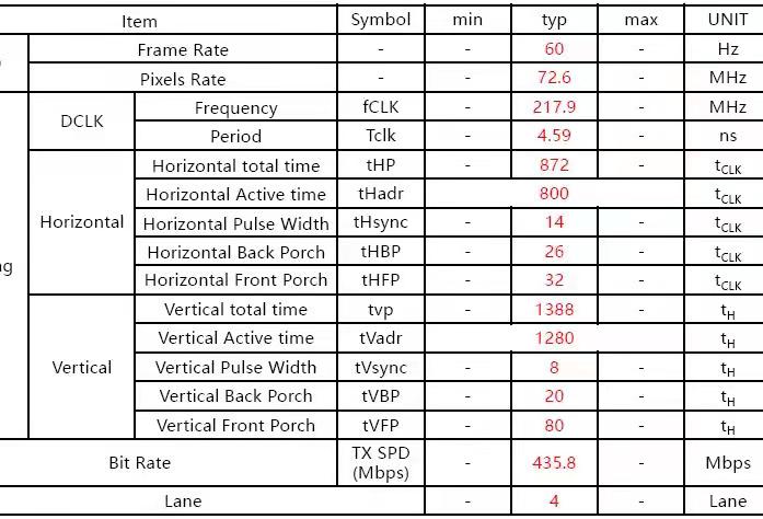
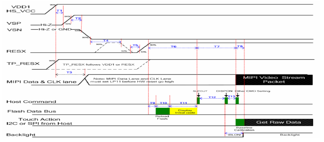
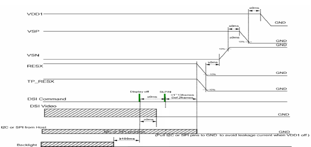
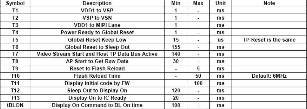
The external screen is Firefly V2 Version
Combining ROC-RK3576-PC DSI interface and screen timing
DSI interface

V2 screen display timing

V2 screen power-on timing

V2 screen power-down timing

V2 screen power-up symbol reference

Add to the system status tree:
//config the backlight
backlight: backlight {
		...
        status = "okay";
        compatible = "pwm-backlight";
        enable-gpios = <&gpio3 RK_PA2 GPIO_ACTIVE_HIGH>;
        pwms = <&pwm1_6ch_1 0 50000 1>;

        ...
}
&pwm1_6ch_1 {
	status = "okay";
	pinctrl-0 = <&pwm1m0_ch1>;
};

//enable the  dsi0 logo og startup
&route_dsi {
    status = "okay";
    connect = <&vp1_out_dsi>;
};

//connect dsi0 with Port3
&dsi_in_vp0 {
	status = "disabled";
};

&dsi_in_vp1 {
    status = "okay";
};

//enable dsi(Note:this part is more important which contants the timing of the display)
&dsi {
	status = "okay";
	//rockchip,lane-rate = <1000>;
	dsi_panel: panel@0 {
		status = "okay";
		compatible = "simple-panel-dsi";
		reg = <0>;

		//select the backlight node of the previous configuration
		backlight = <&backlight>;

		//sets the LCD enable pin
		enable-gpios = <&gpio0 RK_PC5 GPIO_ACTIVE_HIGH>

		//sets the LCD reset pin
		reset-gpios = <&gpio0 RK_PB4 GPIO_ACTIVE_LOW>;

		//sets the timing of startup of LCD
		enable-delay-ms = <50>;
		prepare-delay-ms = <200>;
		reset-delay-ms = <50>;
		init-delay-ms = <55>;
		unprepare-delay-ms = <50>;
		disable-delay-ms = <20>;
		mipi-data-delay-ms = <200>;
		size,width = <120>;
		size,height = <170>;

		//set the output mode of DSI (DPHY). the default mode is Video
		dsi,flags = <(MIPI_DSI_MODE_VIDEO | MIPI_DSI_MODE_VIDEO_BURST | MIPI_DSI_MODE_LPM | MIPI_DSI_MODE_EOT_PACKET)>;

		//sets the output format for DSI pixel data, depending on whether the receiving screen supports the format
		dsi,format = <MIPI_DSI_FMT_RGB888>;

		//set the number of lanes to be used. Default is 4 lanes
		dsi,lanes  = <4>;

		//set the power-on command for the MIPI DSI
		panel-init-sequence = [
			//39 00 04 B9 83 10 2E
			// 15 00 02 CF FF
			05 78 01 11
			05 32 01 29
			//15 00 02 35 00
		];

		//set the power-off command for the MIPI DSI
		panel-exit-sequence = [
			05 00 01 28
			05 00 01 10
		];

		//set the display timing of the LCD screen (this part can be obtained from the corresponding screen, as shown in the figure above)
		disp_timings0: display-timings {
			native-mode = <&dsi0_timing0>;
			dsi0_timing0: timing0 {

				/* the conversion formula for display timing sequence is generally:
				(hactive + hsync-len + hback-porch + hfront-porch)
							x
				( vactive + vsync-len + vback-porch + vfront-porch)x fps
				 = clock-frequency
				*/
				clock-frequency = <72600000>;//<80000000>;
				hactive = <800>;//<768>;
				vactive = <1280>;
				hsync-len = <14>;   //20, 50,10
				hback-porch = <26>; //50, 56,10
				hfront-porch = <32>;//50, 30,180
				vsync-len = <8>;//4
				vback-porch = <20>;//4
				vfront-porch = <80>;//8
				hsync-active = <0>;
				vsync-active = <0>;
				de-active = <0>;
				pixelclk-active = <0>;
			};
		};

		ports {
			#address-cells = <1>;
			#size-cells = <0>;

			port@0 {
				reg = <0>;
				panel_in_dsi: endpoint {
					remote-endpoint = <&dsi_out_panel>;
				};
			};
		};
	};

	ports {
		#address-cells = <1>;
		#size-cells = <0>;

		port@1 {
			reg = <1>;
			dsi_out_panel: endpoint {
			remote-endpoint = <&panel_in_dsi>;
			};
		};
	};
};

//enable the touch function on the screen
&i2c0{
	status = "okay";
	pinctrl-names = "default";
	pinctrl-0 = <&i2c0m1_xfer>;

	hxchipset@48{
		status = "okay";
		compatible = "himax,hxcommon";
		reg = <0x48>;
		//set the reset pin for the touch function
		himax,rst-gpio =  <&gpio0 RK_PD0 GPIO_ACTIVE_HIGH>;

		//sets the interrupt pin for the touch function
		himax,irq-gpio = <&gpio0 RK_PC6 IRQ_TYPE_LEVEL_HIGH>;

		//himax,3v3-gpio = <&gpio0 RK_PB4 GPIO_ACTIVE_HIGH>;
		//himax,pon-gpio = <&gpio0 RK_PB4 GPIO_ACTIVE_HIGH>;
		pinctrl-names = "default";
        	pinctrl-0 = <&touch_int0>;
		//pinctrl-names = "default";
		//pinctrl-0 = <&lcd_tp_int>;

		himax,panel-coords = <0 800 0 1280>;      //Range of touch
		himax,display-coords = <0 800 0 1280>;    //resolution
		report_type = <1>;
	};
};
When configuring MIPI DSI, if there are abnormal phenomena, such as black screen, picture stretching, display noise, etc., you need to pay attention to troubleshooting:
Shows whether the timing configuration is correct, especially the DCLK configuration.
Is the power-on timing correct, in the file
kernel/drivers/gpu/drm/panel/panel-simple.cIn thepanel_simple_prepareandpanel_simple_unpreparefunctions, the power-up timing and gpio port configured in the system status tree are called.If you choose to enable the boot logo during the uboot phase, you also need to troubleshoot the
u-boot/drivers/video/drm/rockchip_panel.candpanel_simple_preparefunctions in thepanel_simple_unpreparefile.Take an oscilloscope to see if the power-on timing is correct, mainly to confirm whether the timing between the LCD enable pin, the reset pin and the on-screen power-on command is correct.
3.2. ROC-RK3576-PC Multiscreen scene configuration
Here are some general scenarios about Portx and configuration methods between display controllers:
HDMI(4K@120Hz) + Display Port + MIPI DSI (2K@60Hz)
&hdmi_in_vp0 {
        status = "okay";
};

&dsi_in_vp1 {
        status = "okay";
};

&dp0_in_vp2 {
        status = "okay";
};
3.3. Debug method
Set resolution in the system
System mouse click: ‘Settings — > Display — > HDMI- > resolution settings’
Get the edid of HDMI/Display Port (take HDMI as an example)
:/ # busybox hexdump /sys/class/drm/card0-HDMI-A-1/edid
0000000 ff00 ffff ffff 00ff 040d 0030 0001 0000
0000010 1e01 0301 8b80 784e 502a a31f 4959 2497
0000020 4fbb 2153 0008 8081 c081 0081 c0d1 7c61
0000030 fc81 0101 0101 7404 7c00 70f6 805a 58fc
0000040 008a 1072 0053 1e00 3a02 1880 3871 402d
0000050 2c58 0045 1072 0053 1e00 0000 fc00 4300
0000060 5348 5648 200a 2020 2020 2020 0000 fd00
0000070 1700 0f4c 1e50 0a00 2020 2020 2020 4a01
0000080 0302 f07c 015f 0302 0504 0706 1190 1312
0000090 1514 1f16 2220 5e5d 605f 6261 6564 c266
00000a0 c4c3 c7c6 0932 0717 0715 5750 0106 0467
00000b0 3d03 c007 7e5f e601 4611 00d0 8070 4783
00000c0 0000 036e 000c 0020 3cb8 0020 0180 0302
00000d0 6d04 5dd8 01c4 8078 2267 0000 67cf e51f
00000e0 000f 3000 e363 0506 e301 c305 e201 ff00
00000f0 01eb d046 4800 42af 38a2 d727 0000 a400
0000100
Get the resolutions supported by HDMI/Display Port (take HDMI as an example)
:/ # cat /sys/class/drm/card0-HDMI-A-1/modes
3840x2160
7680x4320
7680x4320
7680x4320
7680x4320
7680x4320
7680x4320
7680x4320
7680x4320
4096x2160
4096x2160
4096x2160
4096x2160
4096x2160
4096x2160
4096x2160
Get the connection status of HDMI/Display Port (take HDMI as an example)
:/ # cat /sys/class/drm/card0-HDMI-A-1/status
connected
Get information on the Video Portx in use on the system (with the connected display controller)
:/ # cat /d/dri/0/summary
Video Port0: ACTIVE
    Connector: HDMI-A-1
        bus_format[2026]: UYYVYY8_0_5X24
        overlay_mode[1] output_mode[e] color_space[3], eotf:0
    Display mode: 7680x4320p60
        clk[2376000] real_clk[2376000] type[40] flag[5]
        H: 7680 8232 8408 9000
        V: 4320 4336 4356 4400
    Cluster0-win0: ACTIVE
        win_id: 0
        format: AB24 little-endian (0x34324241)[AFBC] SDR[0] color_space[0] glb_alpha[0xff]
        rotate: xmirror: 0 ymirror: 0 rotate_90: 0 rotate_270: 0
        csc: y2r[0] r2y[1] csc mode[1]
        zpos: 0
        src: pos[0, 0] rect[3840 x 2160]
        dst: pos[0, 0] rect[7680 x 4320]
        buf[0]: addr: 0x0000000010971000 pitch: 15360 offset: 0
Video Port1: DISABLED
Video Port2: DISABLED
Video Port3: DISABLED
Generally, if you encounter the problem that HDMI/Display Port cannot be displayed, you need to execute the above command to see if the connection status, edid and resolution are correct.
