14. UART
14.1. Introduction
ITX-3588J supports RS232, RS485, UART0, UART1 interfaces
RS232 and UART0 can only be used
RS485 and UART1 can only be used
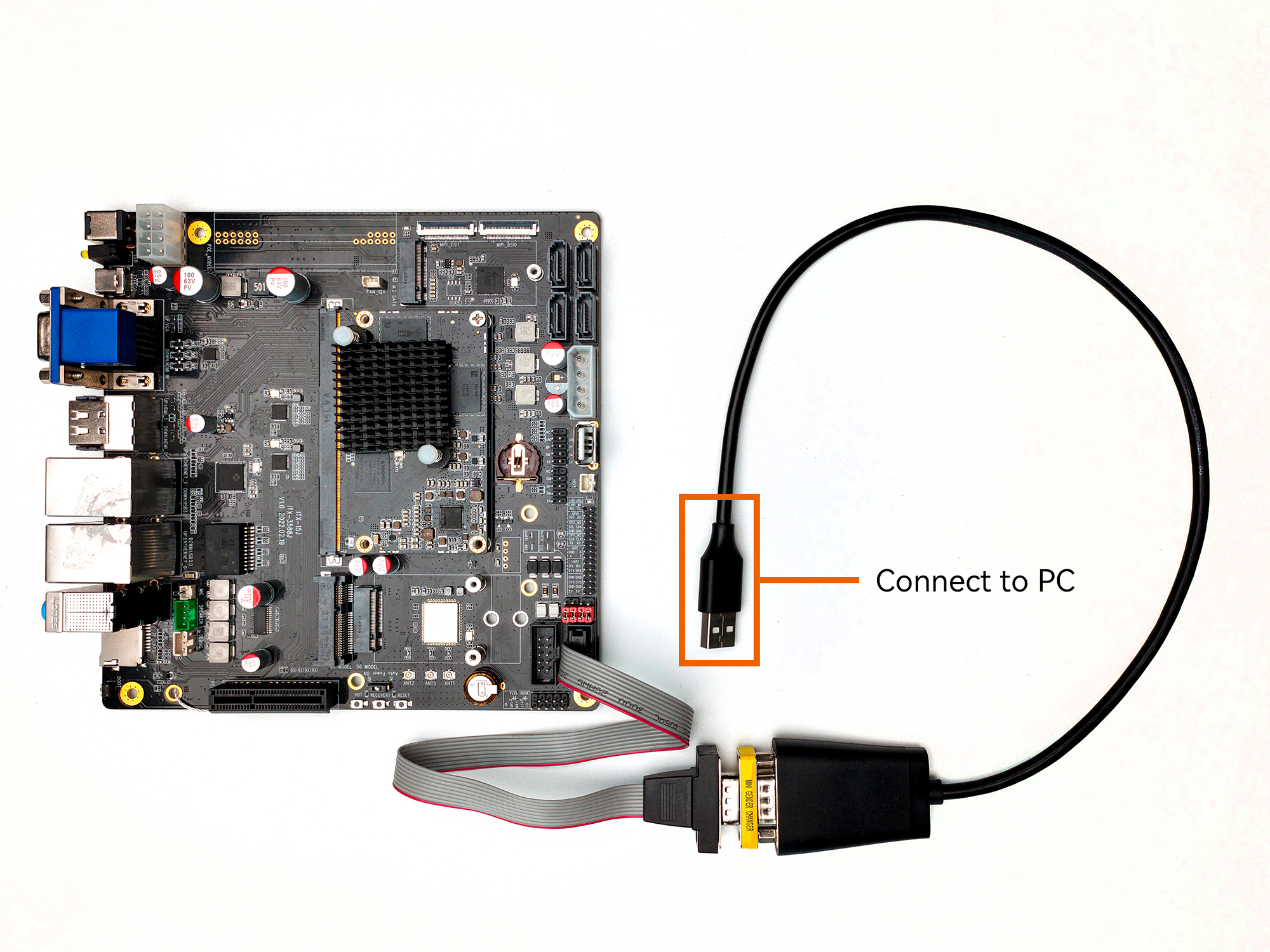
The serial interface diagram of the ITX-3588J development board is as follows:
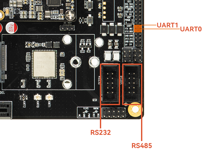
How to use jumper to select RS232 or UART0, RS485 or UART1:
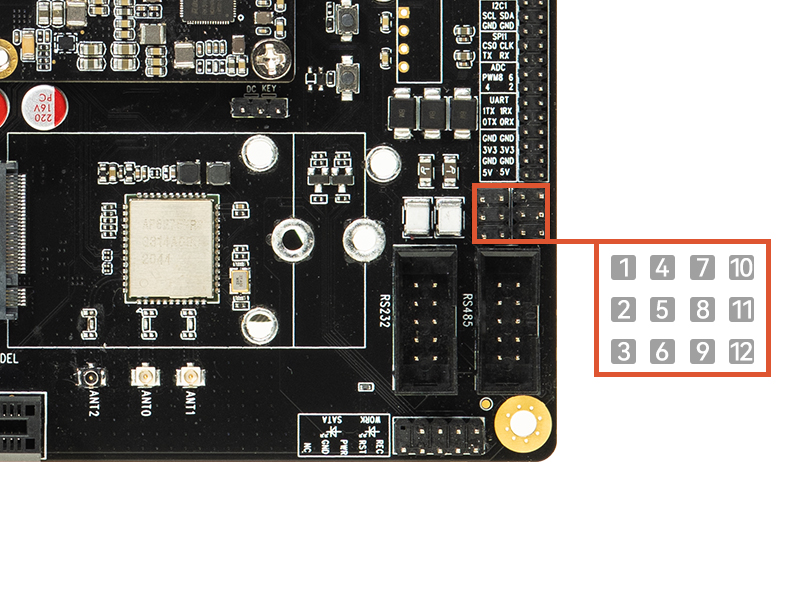
RS232:
8and9are shorted,11and12are shortedUART0:
8and7are shorted,11and10are shortedRS485:
2and3are shorted,5and6are shortedUART1:
2and1are shorted,5and4are shorted
For example, if you choose to use RS232 or RS485, the jumper connection diagram is as follows:
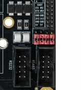
RS232 and RS485 are recommended to use official FC10 to DP9 serial port cable. The serial port cable sequence of different manufacturers may be different, which will cause the serial port to fail to communicate.

14.2. DTS configuration
The RS232 interface of the development board is extended by the main control UART0, and the RS485 interface is extended by the main control UART1.
File path kernel-5.10/arch/arm64/boot/dts/rockchip/rk3588-firefly-itx-3588j.dtsi
/* uart/232/485 */
&uart0{
    pinctrl-0 = <&uart0m2_xfer>;
    status = "okay";
};

&uart1{
    pinctrl-0 = <&uart1m1_xfer>;
    status = "okay";
};
After configuring the serial port, the nodes on the software corresponding to the hardware interface are:
RS232 or UART0:   /dev/ttyS0
RS485 or UART1:  /dev/ttyS1
14.3. Send and receive verification
Users can use different host’s USB-to-serial adapters to send and receive data to the serial port of the development board according to different interfaces. For example, the debugging steps of RS485 are as follows:
(1) Connect the hardware
RS485 to connect FC10 to DP9 serial cable;
FC10 to DP9 serial cable to connect host serial adapter (USB to 485 serial port module);
Host serial adapter (USB to 485 to serial module) connect to the host
(2) Development board sends, host receives
# The host terminal executes first:
# /dev/ttyUSB0 is the node of the host serial adapter, modify it according to the actual situation
cat /dev/ttyUSB0

# The development board debugs the serial port terminal and executes:
# /dev/ttyS1 is the RS485 node
echo "firefly RS485 test..." > /dev/ttyS1
The host terminal will receive the string “firefly RS485 test…”
(3) Host sends, development board receives
# To debug the serial terminal on the development board, execute first:
# /dev/ttyS1 is the RS485 node
busybox  stty -echo -F /dev/ttyS1       # turn off echo
cat /dev/ttyS1

# The host terminal executes:
# /dev/ttyUSB0 is the node of the host serial adapter, modify it according to the actual situation
echo "firefly RS485 test..." > /dev/ttyUSB0
The development board debugs the serial terminal to receive the string “firefly RS485 test…”