11. RTC
11.1. Introduction
ITX-3588J development BOARD uses HYM8563 as RTC(Real Time Clock), HYM8563 is a low power CMOS real-time Clock/calendar chip, it provides a programmable Clock output, an interrupt Output and a power down detector, all addresses and data are passed serially through the I2C bus interface.The maximum bus speed is 400Kbits/s, after each read and write data, the embedded word address register will automatically increment
Timing can be based on 32.768kHz crystals in seconds, minutes, hours, weeks, days, months and years
Wide working voltage range :1.0~5.5V
Low resting current: Typical 0.25μA(VDD =3.0V, TA =25°C)
Internal integrated oscillating capacitor
drain open circuit interrupt pin
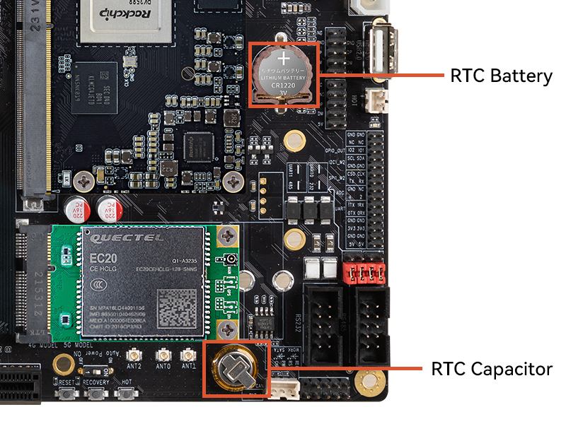
RTC has two power supply options, a button battery and a capacitor. After the 1220 button battery is installed on the development board, the RTC can run normally for a long time after the board is powered off, and the capacitor can ensure the RTC to run in a short time. The position of button battery base and capacitor is shown in the following figure:
11.2. Driver RTC
The dts configuration reference in the Android SDK: kernel-5.10/arch/arm64/boot/dts/rockchip/rk3588-diff.dtsi and
kernel-5.10/arch/arm64/boot/dts/rockchip/rk3588-firefly-itx-3588j.dtsi
&i2c6 {
    status = "okay";
    pinctrl-names = "default";
    pinctrl-0 = <&i2c6m0_xfer>;
    clock-frequency = <400000>;

    hym8563: hym8563@51 {
        compatible = "haoyu,hym8563";
        reg = <0x51>;
        #clock-cells = <0>;
        clock-frequency = <32768>;
        clock-output-names = "hym8563";
        pinctrl-names = "default";
        pinctrl-0 = <&hym8563_int>;
        interrupt-parent = <&gpio0>;
        interrupts = <RK_PB0 IRQ_TYPE_LEVEL_LOW>;
        wakeup-source;
        status = "disabled";
    };
};
Driver Reference: kernel-5.10/drivers/rtc/rtc-hym8563.c
11.3. Interface usage
Linux provides three user-space call interfaces. The corresponding path in the ITX-3588J development board is:
SYSFS Interface :
/sys/class/rtc/rtc0/PROCFS Interface :
/proc/driver/rtcIOCTL Interface :
/dev/rtc0
11.3.1. SYSFS Interface
You can directly use the interface below cat and echo operations /sys/class/rtc/rtc0/.
For example, check the date and time of the current RTC:
# cat /sys/class/rtc/rtc0/date
2013-01-18
# cat /sys/class/rtc/rtc0/time
09:36:10
Set the startup time, such as starting up after 120 seconds:
#Start the machine regularly after 120 seconds
echo +120 >  /sys/class/rtc/rtc0/wakealarm
# View boot time
cat /sys/class/rtc/rtc0/wakealarm
#To turn it off
reboot -p
11.3.2. PROCFS Interface
Print RTC related information:
# cat /proc/driver/rtc
rtc_time        : 06:53:50
rtc_date        : 2022-06-21
alrm_time       : 06:55:05
alrm_date       : 2022-06-21
alarm_IRQ       : yes
alrm_pending    : no
update IRQ enabled      : no
periodic IRQ enabled    : no
periodic IRQ frequency  : 1
max user IRQ frequency  : 64
24hr            : yes
11.3.3. IOCTL Interface
You can use ioctl to control /dev/rtc0.
Please refer to the document rtc.txt for detailed instructions.