4. Display 使用
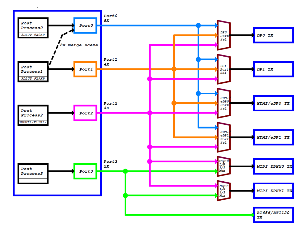
RK3588S 拥有四路 Video 输出端口,每一个 Video 输出端口都绑定了固定的显示控制器,如 Port0 可以用于与 DP0、DP1、HDMI/eDP0 和 HDMI/eDP1 等显示控制器的连接,其他 Portx 以此类推。
每一个 Portx 都有各自所能输出的最大分辨率:
Port0 最大可以输出 7680x4320@60Hz
Port1 最大可以输出 4096x2304@60Hz
Port2 最大可以输出 4096x2304@60Hz
Port3 最大可以输出 1920x1080@60Hz
软件上如果把 HDMI0 显示控制器连接在 Port0 上,且硬件 phy 支持 HDMI2.1,则 HDMI0 支持 8K@60Hz 的输出。
如果给每一个 Portx 都单独分配一个显示控制器的话,便可支持同一时间的四屏同显(异显)。
但从软件的角度上,有以下的配置注意事项:
RK3588S 在做 8K 输出的时候,其实芯片内部是同时使用了 Port0 以及 Port1 的资源,只是借用 Port0 口做输出,所以当与 Port0 连接的显示控制器连接外部的 8K 显示器做输出的时候,与 Port1 连接的显示控制器工作会有异常。
例如 HDMI0(接Port0) 接 8K 输出的时候,DP0(接Port1) 显示会有异常。只有当 Port0 输出小于等于4K@60Hz 的时候,Port1 才可以正常输出 4K@60Hz。
4.1. AIO-3588SG 显示接口的配置
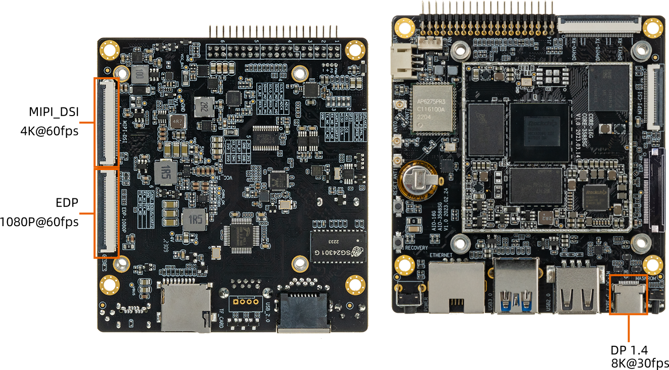
AIO-3588SG 有三种显示输出接口,分别是 EDP 、Display Port 以及 MIPI DSI,接口图如下所示:
EDP/ Display Port/ MIPI DSI1
下面对各个显示输出接口的配置和使用作基本的介绍,详细内容可以参考文件:
kernel-5.10/arch/arm64/boot/dts/rockchip/rk3588s-firefly-aio-3588sg.dtsikernel-5.10/arch/arm64/boot/dts/rockchip/rk3588s-firefly-aio-3588sg-mipi101-M101014-BE45-A1.dtsikernel-5.10/arch/arm64/boot/dts/rockchip/rk3588s-firefly-aio-3588sg-edp-NV156FHM-T06.dtsi
4.1.1. Display Port
AIO-3588SG 有一个 Display Port 显示输出接口,支持 DP TX 1.4a 协议,分辨率最高可以支持 7680x4320@30Hz(取决于连接的portx)。
4.1.1.1. 软件配置
Display Port 软件上表示为 dp0,在设备树上添加:
// 打开 dp0 的音频输出功能
&spdif_tx2{
        status = "okay";
};

&dp0_sound{
        status = "okay";
};

//打开 dp0 功能
&dp0 {
        status = "okay";
};

//把 dp0 的显示接口连接在 port2
&dp0_in_vp2 {
        status = "okay";
};

//使能对应 Type-C 口的 PD 电源芯片
&usbc0{
        status = "okay";
        interrupt-parent = <&gpio0>;
        interrupts = <RK_PC4 IRQ_TYPE_LEVEL_LOW>;
};

/* disable for charge ic sc8886 */
//vbus电压由充电ic控制
&vbus5v0_typec_pwr_en {
    status = "disabled";
};

/* 注意:目前 dp0 暂不支持 开机 logo 的显示功能 */
这里要注意,SDK 默认的软件配置是把 dp0 连接在 vp2 上面,这样会导致 dp0 最高只能输出 4096x2304@60Hz,所以如果需要 7680x4320@30Hz 的功能,需要把 dp0 连接在 vp0 上面
4.1.2. MIPI DSI
AIO-3588SG 有一路 MIPI DSI 显示输出接口,支持 DPHY2.0 和 4 Lane 的数据输出,最高可输出 4096x2304@60Hz(取决于连接的 Portx)。
4.1.2.1. 软件配置
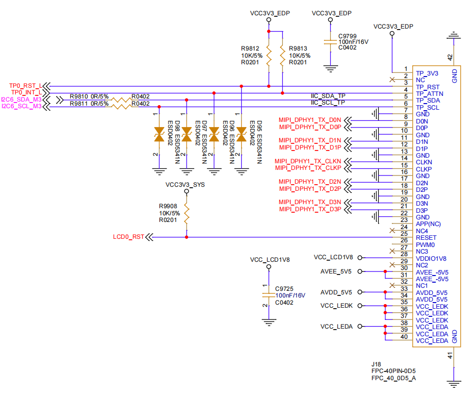
DSI的软件配置,外接的屏幕是 101-M101014-BE45-A1 显示屏,DSI 软件上表示为 dsi1。
结合 AIO-3588SG 的 DSI0 接口和屏幕时序
DSI 接口
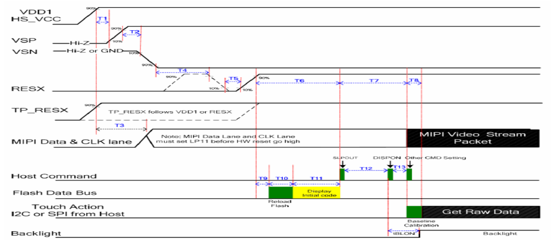
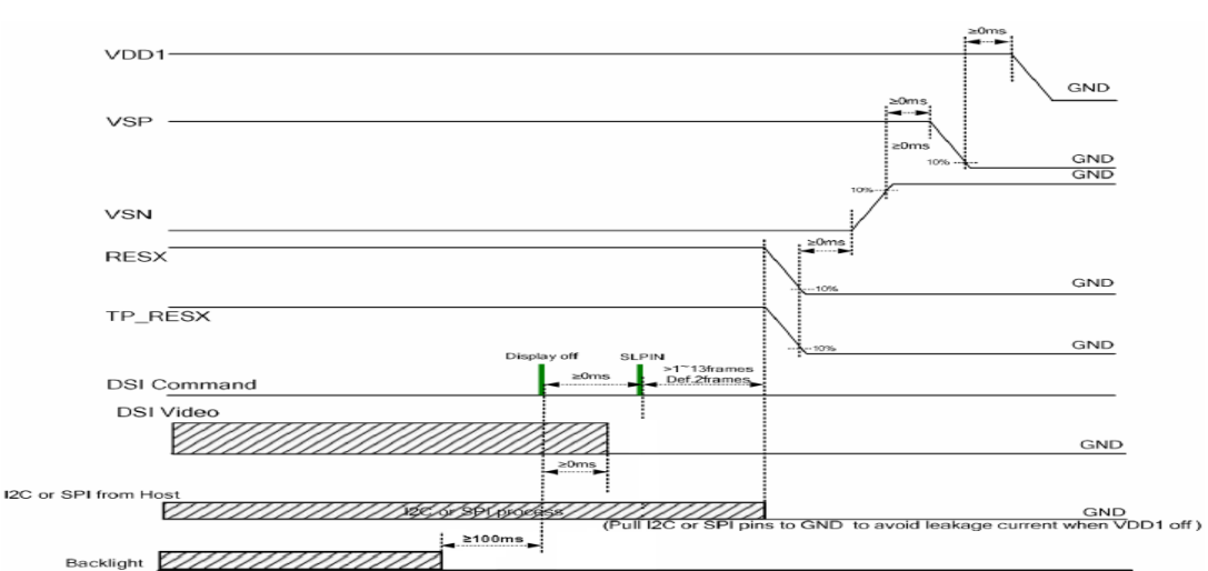
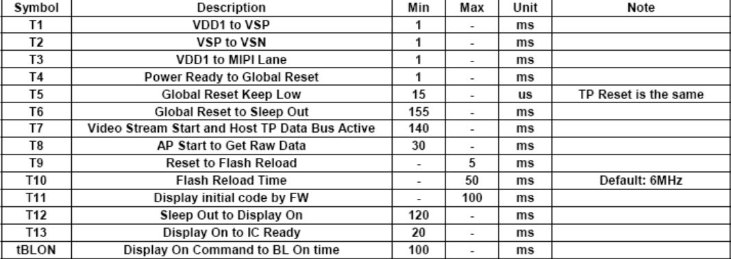
V2 屏幕显示时序
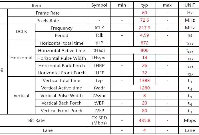
V2 屏幕上电时序
V2 屏幕下电时序
V2 屏幕上下电符号参考
在设备树上添加:
//设置屏幕的电源
vcc3v3_tp_en_regulator: vcc3v3-tp-en-regultor{
		status = "okay";
		compatible = "regulator-fixed";
		regulator-name = "vcc3v3_tp_en";
		regulator-always-on;
		enable-active-high;
        gpio = <&pca9555 PCA_IO0_6 GPIO_ACTIVE_HIGH>;
	};

//设置屏幕的背光
backlight_dsi1: backlight-dsi1 {
        status = "okay";
        compatible = "pwm-backlight";
        enable-gpios = <&gpio4 RK_PB7 GPIO_ACTIVE_HIGH>;
		pwms = <&pwm3 0 50000 1>;

        ...
}

&pwm3 {
    pinctrl-0 = <&pwm3m3_pins>;
    status = "okay";
};

//设置 dsi 的开机 logo
&route_dsi1 {
    status = "okay";
    connect = <&vp3_out_dsi1>;
};

//把 dsi0 连接在 Port3 上
&dsi1_in_vp3 {
    status = "okay";
};

&dsi1_in_vp2 {
    status = "disabled";
};

//打开 DPHY
&mipi_dcphy1 {
    status = "okay";
};

//设置vop频率
&vop {
    assigned-clocks = <&cru ACLK_VOP>;
    assigned-clock-rates = <500000000>;
};

//打开 dsi1(注意这一部分较重要,涉及到屏幕的上电时序)
&dsi1 {
    status = "okay";
    //rockchip,lane-rate = <1000>;
    dsi_panel: panel@0 {
        status = "okay";
        compatible = "simple-panel-dsi";
        reg = <0>;

		//选择之前的配置的背光节点
		backlight = <&backlight_dsi1>;

		//选择之前的配置的电源
		power-supply = <&vcc3v3_tp_en_regulator>;

		//设置 LCD 使能引脚
		enable-gpios = <&pca9555 PCA_IO0_5 GPIO_ACTIVE_HIGH>;

		//设置 LCD 复位引脚
		reset-gpios = <&pca9555 PCA_IO0_4 GPIO_ACTIVE_LOW>;

		//设置 LCD 屏幕的上下电时序
		enable-delay-ms = <50>;
		prepare-delay-ms = <200>;
		reset-delay-ms = <50>;
		init-delay-ms = <55>;
		unprepare-delay-ms = <50>;
		disable-delay-ms = <20>;
		mipi-data-delay-ms = <200>;
		size,width = <120>;
		size,height = <170>;

		//设置 DSI(DPHY)的输出模式,一般默认为 Video 模式
		dsi,flags = <(MIPI_DSI_MODE_VIDEO | MIPI_DSI_MODE_VIDEO_BURST | MIPI_DSI_MODE_LPM | MIPI_DSI_MODE_EOT_PACKET)>;

		//设置 DSI 像素数据的输出格式,这部分的设置取决于接收端的屏幕是否支持该格式
		dsi,format = <MIPI_DSI_FMT_RGB888>;

		//设置使用的 lane 数量,默认为 4 lane
		dsi,lanes  = <4>;

		//设置 MIPI DSI 的上电指令
		panel-init-sequence = [
			//39 00 04 B9 83 10 2E
			// 15 00 02 CF FF
			05 78 01 11
			05 32 01 29
			//15 00 02 35 00
		];

		//设置 MIPI DSI 的下电指令
		panel-exit-sequence = [
			05 00 01 28
			05 00 01 10
		];

		//设置 LCD 屏幕的显示时序(该部分内容一般都可以从对应屏幕的 datasheet 中获取,如上图所示)
		disp_timings0: display-timings {
			native-mode = <&dsi0_timing0>;
			dsi0_timing0: timing0 {

				/* 显示时序的换算公式一般为:
				(hactive + hsync-len + hback-porch + hfront-porch)
							x
				( vactive + vsync-len + vback-porch + vfront-porch)x fps
				 = clock-frequency
				*/
				clock-frequency = <72600000>;//<80000000>;
				hactive = <800>;//<768>;
				vactive = <1280>;
				hsync-len = <14>;   //20, 50,10
				hback-porch = <26>; //50, 56,10
				hfront-porch = <32>;//50, 30,180
				vsync-len = <8>;//4
				vback-porch = <20>;//4
				vfront-porch = <80>;//8
				hsync-active = <0>;
				vsync-active = <0>;
				de-active = <0>;
				pixelclk-active = <0>;
			};
		};

		ports {
			#address-cells = <1>;
			#size-cells = <0>;

			port@0 {
				reg = <0>;
				panel_in_dsi: endpoint {
					remote-endpoint = <&dsi_out_panel>;
				};
			};
		};
	};

	ports {
		#address-cells = <1>;
		#size-cells = <0>;

		port@1 {
			reg = <1>;
			dsi_out_panel: endpoint {
			remote-endpoint = <&panel_in_dsi>;
			};
		};
	};
};

//使能屏幕的触摸功能
&i2c6{
	hxchipset@48{
		status = "okay";
		compatible = "himax,hxcommon";
		reg = <0x48>;
		//设置触摸功能的复位引脚
		himax,rst-gpio =  <&gpio1 RK_PB2 GPIO_ACTIVE_HIGH>;

		//设置触摸功能的中断引脚
		himax,irq-gpio = <&gpio1 RK_PA7 IRQ_TYPE_LEVEL_HIGH>;

		pinctrl-names = "default";
        	pinctrl-0 = <&touch_int0>;

		himax,panel-coords = <0 800 0 1280>;      //触摸范围
		himax,display-coords = <0 800 0 1280>;    //分辨率
		report_type = <1>;
	};
};
在配置 MIPI DSI的时候,如果出现异常现象,如黑屏,画面拉伸,显示有噪点等,需要注意排查:
显示时序是否配置正确,尤其是 DCLK 的配置。
上下电时序是否正确,在文件
kernel-5.10/drivers/gpu/drm/panel/panel-simple.c中的panel_simple_prepare和panel_simple_unprepare函数内,调用了设备树中所配置的上下电时序和 gpio 口。如果选择在 uboot 阶段开启开机 logo, 那么还需要排查
u-boot/drivers/video/drm/rockchip_panel.c文件内的panel_simple_prepare和panel_simple_unprepare函数。搭示波器看一下上电时序是否正确,主要是确认 LCD 使能引脚、复位引脚和屏幕上电指令间的时序是否正确。
4.1.3. eDP
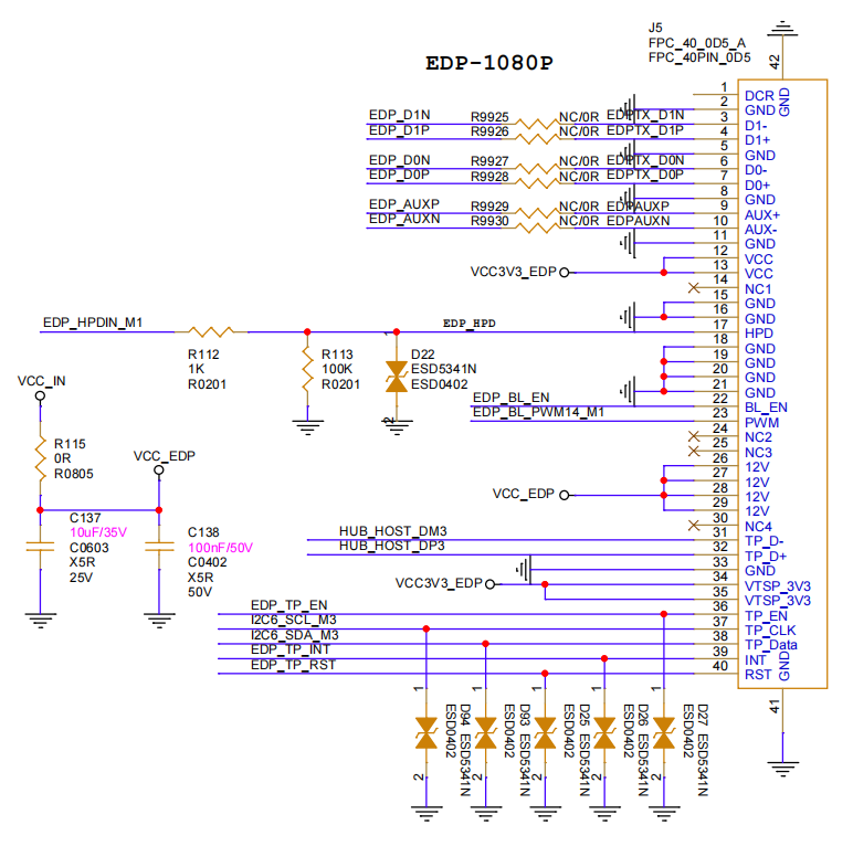
AIO-3588SG 有一路 EDP 显示输出接口,最高可输出 4096x2304@60Hz(取决于连接到portx)。
4.1.3.1. 软件配置
EDP 接口
屏幕的上下电时序
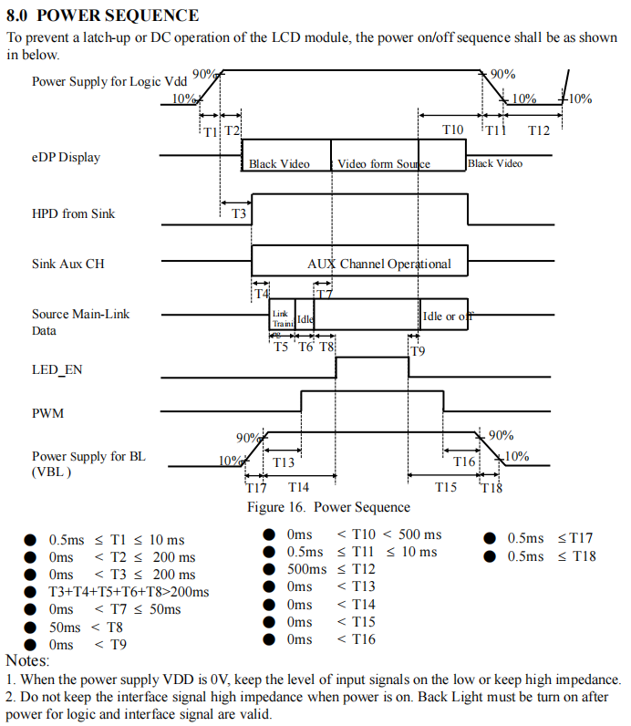
kernel-5.10/arch/arm64/boot/dts/rockchip/rk3588-firefly-aio-3588q-edp_NV156FHM-T06.dts,从该文件中我们可以看到以下语句:
edp_panel: edp-panel {
        compatible = "simple-panel";
        status = "okay";

        //选择配置的背光节点
        backlight = <&backlight_edp>;

        //设置 LCD 电源控制硬件
        pwr-gpios = <&pca9555 PCA_IO0_6 GPIO_ACTIVE_HIGH>;
        pwr-delay-ms = <200>;

        //设置 LCD 使能引脚
        enable-gpios = <&pca9555 PCA_IO0_2 GPIO_ACTIVE_HIGH>; // EDP_BL_EN

        //EDP显示时序配置
        display-timings {
            native-mode = <&timing0>;
            timing0: timing0 {
                clock-frequency = <140000000>;
                hactive = <1920>;
                vactive = <1080>;
                hfront-porch = <40>;
                hsync-len = <40>;
                hback-porch = <80>;
                vfront-porch = <16>;
                vsync-len = <8>;
                vback-porch = <16>;
                hsync-active = <0>;
                vsync-active = <0>;
                de-active = <0>;
                pixelclk-active = <0>;
            };
        };

        ports {
            panel_in_edp1: endpoint {
                remote-endpoint = <&edp1_out_panel>;
            };
        };
    };

    //设置屏幕的背光
    backlight_edp: backlight-edp {
        status = "okay";
        compatible = "pwm-backlight";
        pwms = <&pwm14 0 500000 0>;

        ...
};

&pwm14 {
    pinctrl-0 = <&pwm14m1_pins>;
    status = "okay";
};

&edp0 {
    //force-hpd;
    hpd-gpios = <&gpio1 RK_PA6 GPIO_ACTIVE_HIGH>;
    status = "okay";

    ports {
        port@1 {
            reg = <1>;

            edp1_out_panel: endpoint {
                remote-endpoint = <&panel_in_edp1>;
            };
        };
    };
};

//设置 edp0 的开机 logo
&route_edp0  {
    status = "okay";
    connect = <&vp2_out_edp1>;
};

//把 edp0 连接在 Port2 上
&edp0_in_vp2 {
    status = "okay";
};

&hdptxphy0 {
    status = "okay";
};

//使能屏幕的触摸功能
&i2c6{
    status = "okay";

    goodix_ts@5d {
        status = "okay";
        compatible = "goodix,gt9xxx";
        reg = <0x5d>;
        interrupt-parent = <&gpio1>;
        interrupts = <0 17 0x2008 0>;

        //设置触摸功能的电源控制引脚
        goodix,pwr-gpio = <&pca9555 PCA_IO0_1 GPIO_ACTIVE_HIGH>;

        //设置触摸功能的复位引脚
        goodix,rst-gpio = <&pca9555 PCA_IO0_0 GPIO_ACTIVE_HIGH>;

        //设置触摸功能的中断引脚
        goodix,irq-gpio = <&gpio1 RK_PA4 IRQ_TYPE_LEVEL_LOW>;
        flip-x = <0>;
        flip-y = <0>;

        ...
    };
};
4.2. 调试手段
在系统中设置分辨率
系统鼠标点击:‘设置->显示->HDMI->分辨率设置’
获取 HDMI/Display Port 的 edid(以 HDMI 为例)
:/ # busybox hexdump /sys/class/drm/card0-HDMI-A-1/edid
0000000 ff00 ffff ffff 00ff 040d 0030 0001 0000
0000010 1e01 0301 8b80 784e 502a a31f 4959 2497
0000020 4fbb 2153 0008 8081 c081 0081 c0d1 7c61
0000030 fc81 0101 0101 7404 7c00 70f6 805a 58fc
0000040 008a 1072 0053 1e00 3a02 1880 3871 402d
0000050 2c58 0045 1072 0053 1e00 0000 fc00 4300
0000060 5348 5648 200a 2020 2020 2020 0000 fd00
0000070 1700 0f4c 1e50 0a00 2020 2020 2020 4a01
0000080 0302 f07c 015f 0302 0504 0706 1190 1312
0000090 1514 1f16 2220 5e5d 605f 6261 6564 c266
00000a0 c4c3 c7c6 0932 0717 0715 5750 0106 0467
00000b0 3d03 c007 7e5f e601 4611 00d0 8070 4783
00000c0 0000 036e 000c 0020 3cb8 0020 0180 0302
00000d0 6d04 5dd8 01c4 8078 2267 0000 67cf e51f
00000e0 000f 3000 e363 0506 e301 c305 e201 ff00
00000f0 01eb d046 4800 42af 38a2 d727 0000 a400
0000100
获取 HDMI/Display Port 所支持的分辨率(以 HDMI 为例)
:/ # cat /sys/class/drm/card0-HDMI-A-1/modes
3840x2160
7680x4320
7680x4320
7680x4320
7680x4320
7680x4320
7680x4320
7680x4320
7680x4320
4096x2160
4096x2160
4096x2160
4096x2160
4096x2160
4096x2160
4096x2160
获取 HDMI/Display Port 的连接状态(以 HDMI 为例)
:/ # cat /sys/class/drm/card0-HDMI-A-1/status
connected
获取系统中正在使用的 Video Portx(与所连接的显示控制器) 信息
:/ # cat /d/dri/0/summary
Video Port0: ACTIVE
    Connector: HDMI-A-1
        bus_format[2026]: UYYVYY8_0_5X24
        overlay_mode[1] output_mode[e] color_space[3], eotf:0
    Display mode: 7680x4320p60
        clk[2376000] real_clk[2376000] type[40] flag[5]
        H: 7680 8232 8408 9000
        V: 4320 4336 4356 4400
    Cluster0-win0: ACTIVE
        win_id: 0
        format: AB24 little-endian (0x34324241)[AFBC] SDR[0] color_space[0] glb_alpha[0xff]
        rotate: xmirror: 0 ymirror: 0 rotate_90: 0 rotate_270: 0
        csc: y2r[0] r2y[1] csc mode[1]
        zpos: 0
        src: pos[0, 0] rect[3840 x 2160]
        dst: pos[0, 0] rect[7680 x 4320]
        buf[0]: addr: 0x0000000010971000 pitch: 15360 offset: 0
Video Port1: DISABLED
Video Port2: DISABLED
Video Port3: DISABLED
一般如果遇到 HDMI/Display Port 无法显示的问题,都需要先执行上面的命令去看一下连接状态、edid 和分辨率是否正确。
