12. UART
12.1. Introduction
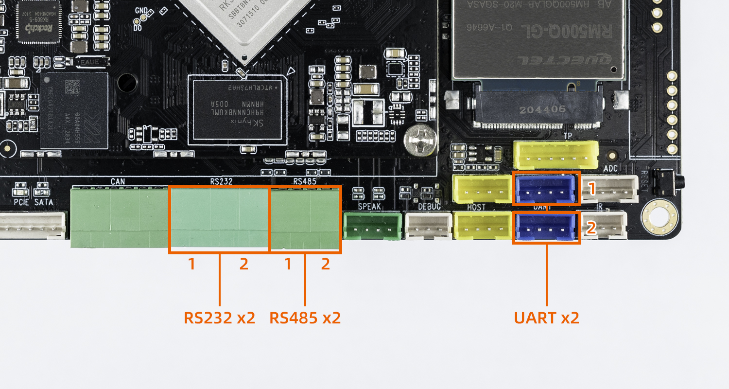
AIO-3568J supports UART、RS232、RS485 interfaces
UARTx2
RS485x2
RS232x2
The RS232 of the board is extended from RK3568 uart3 and uart4, whereas the interfaces UART and RS485 of the board are extended from SPI bridge/extension chip WK2124.
SPI bridge/extension chip WK2124 with functions of four enhanced serial ports (UART), among them:
the baud rate, word length and check format of each subchannel UART can be set independently, and the maximum communication rate of 2Mbps can be provided
each sub-channel has 256 BYTE FIFO, which can be programmed according to user requirements.
has a subserial port to receive FIFO timeout interrupts.
supports start bit error detection.
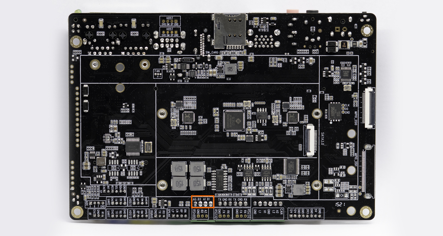
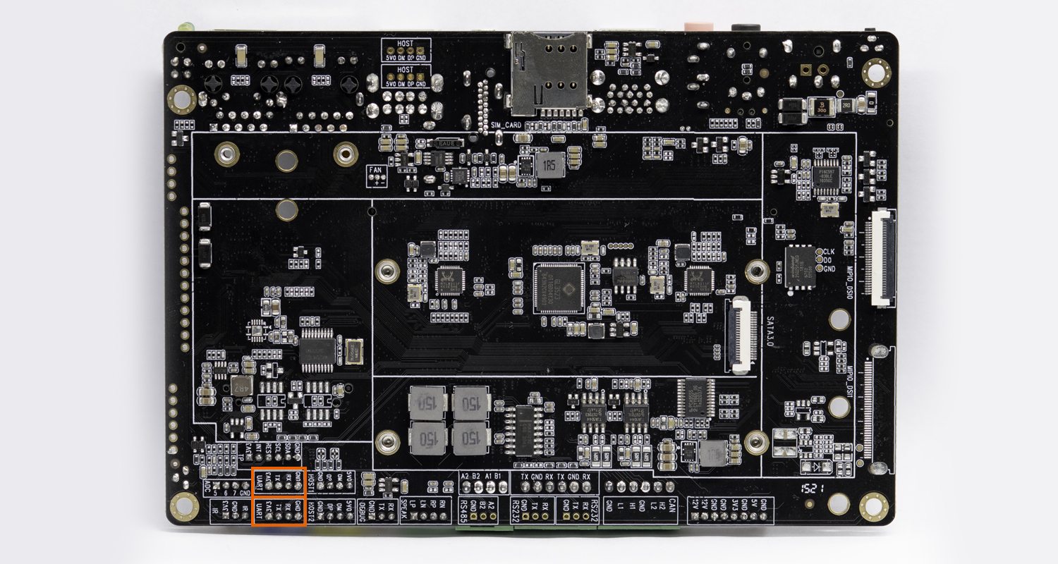
The serial interface diagram of the AIO-3568J development board is as follows:
12.2. DTS configuration
File kernel/arch/arm64/boot/dts/rockchip/rk3568-firefly-port.dtsi has the definition of spi to uart related nodes:
&spi1 {
        status = "disabled";
        max-freq = <48000000>;
        dev-port = <0>;
        pinctrl-0 = <&spi1m1_pins>;
        pinctrl-1 = <&spi1m1_pins_hs>;

        spi_wk2xxx: spi_wk2xxx@00{
                status = "disabled";
                compatible = "firefly,spi-wk2xxx";
                reg = <0x00>;
                spi-max-frequency = <10000000>;
                power-gpio = <&pca9555 PCA_IO1_7 GPIO_ACTIVE_HIGH>;
                reset-gpio = <&pca9555 PCA_IO1_1 GPIO_ACTIVE_HIGH>;
                irq-gpio = <&gpio0 RK_PA6 IRQ_TYPE_EDGE_FALLING>;
                cs-gpio = <&gpio3 RK_PA1 GPIO_ACTIVE_HIGH>;
        };
};
As you can see, enabling the node in the kernel/arch/arm64/boot/dts/rockchip/firefly-rk3568-aioj.dtsi file is available. In addition, SPI1 node needs to be enabled because SPI to UART serial port module used by our board is attached to SPI1. As follows:
&uart3 {
        status = "okay";
};

&uart4 {
        status = "okay";
};

&spi1 {
        status = "okay";
};

&spi_wk2xxx {
        status = "okay";
};
After the serial port is configured, the nodes on the hardware interface corresponding to the software are:
RS485_1:  /dev/ttysWK0
RS485_2:  /dev/ttysWK1
UART1:    /dev/ttysWK2
UART2:    /dev/ttysWK3
RS232_1 :  /dev/ttyS3
RS232_2:   /dev/ttyS4

12.4. Debug method
Users can send and receive data to the serial port of the development board by using the USB to serial port adapter of different host according to different interfaces. For example, the debugging steps of RS485 are as follows:
(1) Connected hardware
Connect A, B and GND pins of development board RS485 with A, B and GND pins of host serial port adapter (USB to 485 to serial port module) respectively.
(2) Open the serial terminal of the host
Input the install Kermit command sudo apt install Kermit on the terminal. After the installation, open Kermit, set the baud rate and connect:
$ sudo kermit
C-Kermit> set line /dev/ttyUSB0
C-Kermit> set speed 9600
C-Kermit> set flow-control none
C-Kermit> connect
/dev/ttyUSB0is the device file for USB to serial port adapter.
(3) Send data to host serial port adapter
The device file for RS485 is /dev/ttysWK0. Run the following commands on the device:
echo firefly RS485 test... > /dev/ttysWK0
The serial terminal in the host can receive a string: “firefly RS485 test… “
(4) Receive data from host serial port adapter
First run the following commands on the device:
cat /dev/ttysWK0
Then enter a string at the host’s serial terminal: Firefly RS485 test..., the device side can see the same string.
(5) Exit kermit connection
The host hit keyboard ctrl+\ and then hit key c, input “exit” and hit enter
C-Kermit>exit
OK to exit? ok