LCD
Introduction
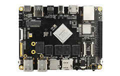
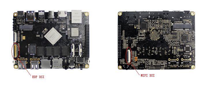
Firefly-RK3399 has two LCD screen interface, one is EDP, one is MIPI, the corresponding interface board position is as follows:
Configure DTS
LCD pins configuration
EDP
The Firefly-RK3399 SDK has an LCD DTS file in kernel/arch/arm64/boot/dts/rockchip/rk3399-firefly-mini-edp.dts, From this file, we can see the following statement:
/ {
	model = "Firefly-RK3399 Board edp (Android)";
	compatible = "rockchip,android", "rockchip,rk3399-firefly-edp", "rockchip,rk3399";

	edp_panel: edp-panel {
		compatible = "lg,lp079qx1-sp0v";
		bus-format = <MEDIA_BUS_FMT_RGB666_1X18>;

		backlight = <&backlight>;

		ports {
			panel_in_edp: endpoint {
				remote-endpoint = <&edp_out_panel>;
			};
		};

		power_ctr: power_ctr {
              rockchip,debug = <0>;
              lcd_en: lcd-en {
                      gpios = <&gpio1 1 GPIO_ACTIVE_HIGH>;
					   pinctrl-names = "default";
					   pinctrl-0 = <&lcd_panel_enable>;
                      rockchip,delay = <20>;
              };
              lcd_rst: lcd-rst {
                      gpios = <&gpio4 29 GPIO_ACTIVE_HIGH>;
					   pinctrl-names = "default";
					   pinctrl-0 = <&lcd_panel_reset>;
                      rockchip,delay = <20>;
               };
       };
	};

	test-power {
		status = "okay";
	};
};

...

&pinctrl {
       lcd-panel {
               lcd_panel_reset: lcd-panel-reset {
                       rockchip,pins = <4 29 RK_FUNC_GPIO &pcfg_pull_up>;
               };
               lcd_panel_enable: lcd-panel-enable {
                       rockchip,pins = <1 1 RK_FUNC_GPIO &pcfg_pull_up>;
               };
       };
};
The power control pins of the LCD are defined here:
lcd_en(GPIO1_A1) GPIO_ACTIVE_HIGH
lcd_rst(GPIO4_D5) GPIO_ACTIVE_HIGH
They are active-high. For details on pin configuration, refer to the GPIO section.
MIPI
Firefly-RK3399 SDK has MIPI DSI DTS files: kernel/arch/arm64/boot/dts/rockchip/rk3399-firefly-mipi/dts. From this file we can see the following statement:
/  {
    model = "Firefly-RK3399 Board mipi (Android)";
    compatible = "rockchip,android", "rockchip,rk3399-firefly-mipi", "rockchip,rk3399";

    test-power {
           status = "okay";
        };
};

&dsi {
        status = "okay";
        dsi_panel: panel {
                compatible ="simple-panel-dsi";
                reg = <0>;
                backlight = <&backlight>;
                dsi,flags = <(MIPI_DSI_MODE_VIDEO | MIPI_DSI_MODE_VIDEO_BURST /*| MIPI_DSI_MODE_VIDEO_SYNC_PULSE*/)>;
                dsi,format = <MIPI_DSI_FMT_RGB888>;
                bus-format = <MEDIA_BUS_FMT_RGB666_1X18>;
                dsi,lanes = <4>;
...
               power_ctr: power_ctr {
               rockchip,debug = <1>;
               lcd_en: lcd-en {
                       gpios = <&gpio1 1 GPIO_ACTIVE_HIGH>;
                                           pinctrl-names = "default";
                                           pinctrl-0 = <&lcd_panel_enable>;
                       rockchip,delay = <10>;
               };
               lcd_rst: lcd-rst {
                       gpios = <&gpio4 29 GPIO_ACTIVE_HIGH>;
                                           pinctrl-names = "default";
                                           pinctrl-0 = <&lcd_panel_reset>;
                       rockchip,delay = <6>;
               };
          };
...

   &pinctrl {
       lcd-panel {
               lcd_panel_reset: lcd-panel-reset {
                       rockchip,pins = <4 29 RK_FUNC_GPIO &pcfg_pull_up>;
               };
               lcd_panel_enable: lcd-panel-enable {
                       rockchip,pins = <1 1 RK_FUNC_GPIO &pcfg_pull_up>;
               };
       };
};
The power control pin of LCD is defined here:
lcd_en:(GPIO1_A1)GPIO_ACTIVE_HIGH

lcd_en:(GPIO4_D5)GPIO_ACTIVE_HIGH
All are high level effective.
Backlight Configuration
In DTS file kernel/arch/arm64/boot/dts/rockchip/rk3399-firefly-core.dtsi configuration of the backlight information.
/ {
    compatible = "rockchip,rk3399-firefly-core", "rockchip,rk3399";
    backlight: backlight {
        status = "disabled";
        compatible = "pwm-backlight";
        pwms = <&pwm0 0 25000 0>;
        brightness-levels = <
              0   1   2   3   4   5   6   7
              8   9  10  11  12  13  14  15
             16  17  18  19  20  21  22  23
             24  25  26  27  28  29  30  31
             32  33  34  35  36  37  38  39
             40  41  42  43  44  45  46  47
             48  49  50  51  52  53  54  55
             56  57  58  59  60  61  62  63
             64  65  66  67  68  69  70  71
             72  73  74  75  76  77  78  79
             80  81  82  83  84  85  86  87
             88  89  90  91  92  93  94  95
             96  97  98  99 100 101 102 103
            104 105 106 107 108 109 110 111
            112 113 114 115 116 117 118 119
            120 121 122 123 124 125 126 127
            128 129 130 131 132 133 134 135
            136 137 138 139 140 141 142 143
            144 145 146 147 148 149 150 151
            152 153 154 155 156 157 158 159
            160 161 162 163 164 165 166 167
            168 169 170 171 172 173 174 175
            176 177 178 179 180 181 182 183
            184 185 186 187 188 189 190 191
            192 193 194 195 196 197 198 199
            200 201 202 203 204 205 206 207
            208 209 210 211 212 213 214 215
            216 217 218 219 220 221 222 223
            224 225 226 227 228 229 230 231
            232 233 234 235 236 237 238 239
            240 241 242 243 244 245 246 247
            248 249 250 251 252 253 254 255>;
        default-brightness-level = <200>;
    };
PWMS attributes: configure PWM. In the example, PWM0 is used by default, and 25000ns is a cycle (40 KHz). The DTS file can be directly used by EDP screen, while the PWM output used by MIPI screen is PWM1. You can see the following statement kernel/arch/arm64/boot/dts/rockchip/rk3399-firefly-mipi.dts:
&backlight{
       status = "okay";
       pwms = <&pwm1 0 25000 0>;
}
Therefore, DTS files need to be modified when used.
brightness-levels property: configure the backlight brightness array, the maximum value is 255, configure the dark and bright areas, and make 255 proportional adjustment to the bright area array. In the example, the dark area is 255-221 and the bright area is 220-0.default-brightness-level attribute: default backlight brightness at boot-up, ranging from 0-255.
Refer specifically to the documentation in the kernel: kernel/Documentation/devicetree/bindings/leds/backlight/pwm-backlight.txt
The configuration of display sequence
EDP
Kernel
Timing writed to panel-simple.c ,using short character to match directly. The following statement is in the drivers/gpu/drm/panel/panel-simple.c file:
static const struct drm_display_mode lg_lp079qx1_sp0v_mode = {
	.clock = 200000,
	.hdisplay = 1536,
	.hsync_start = 1536 + 12,
	.hsync_end = 1536 + 12 + 16,
	.htotal = 1536 + 12 + 16 + 48,
	.vdisplay = 2048,
	.vsync_start = 2048 + 8,
	.vsync_end = 2048 + 8 + 4,
	.vtotal = 2048 + 8 + 4 + 8,
	.vrefresh = 60,
	.flags = DRM_MODE_FLAG_NVSYNC | DRM_MODE_FLAG_NHSYNC,
};

static const struct panel_desc lg_lp097qx1_spa1 = {
	.modes = &lg_lp097qx1_spa1_mode,
	.num_modes = 1,
	.size = {
		.width = 320,
		.height = 187,
	},
};

... ...

   static const struct of_device_id platform_of_match[] = {
	{
		.compatible = "simple-panel",
		.data = NULL,
	},{
......
	}, {
		.compatible = "lg,lp079qx1-sp0v",
		.data = &lg_lp079qx1_sp0v,
	}, {
......
	}, {
		/* sentinel */
	}
 };
MODULE_DEVICE_TABLE(of, platform_of_match); This structure lg_lp079qx1_sp0v_mode configures the LCD parametere.
U-boot
Timing writed to rockchip_panel.c ,using short character to match directly. The following statement is in the drivers/video/rockchip_panel.c file:
static const struct drm_display_mode lg_lp079qx1_sp0v_mode = {
	.clock = 200000,
	.hdisplay = 1536,
	.hsync_start = 1536 + 12,
	.hsync_end = 1536 + 12 + 16,
	.htotal = 1536 + 12 + 16 + 48,
	.vdisplay = 2048,
	.vsync_start = 2048 + 8,
	.vsync_end = 2048 + 8 + 4,
	.vtotal = 2048 + 8 + 4 + 8,
	.vrefresh = 60,
	.flags = DRM_MODE_FLAG_NVSYNC | DRM_MODE_FLAG_NHSYNC,
};
static const struct rockchip_panel g_panel[] = {
	{
		.compatible = "lg,lp079qx1-sp0v",
		.mode = &lg_lp079qx1_sp0v_mode,
	},
    {
		.compatible = "auo,b125han03",
		.mode = &auo_b125han03_mode,
	},
};
This structure lg_lp079qx1_sp0v_mode configures the LCD parameters.
MIPI
Unlike the EDP screen, the Timing of the MIPI screen is written in the DTS file, and the following statement can be seen in kernel/arch/arm64/boot/dts/rockchip/rk3399-firefly-mipi.dts:
disp_timings: display-timings {
    native-mode = <&timing0>;
    timing0: timing0 {
         clock-frequency = <80000000>;
         hactive = <768>;
         vactive = <1024>;
         hsync-len = <20>;   //20, 50
         hback-porch = <130>; //50, 56
         hfront-porch = <150>;//50, 30
         vsync-len = <40>;
         vback-porch = <130>;
         vfront-porch = <136>;
         hsync-active = <0>;
         vsync-active = <0>;
         de-active = <0>;
         pixelclk-active = <0>;
           };
    }
}
Kernel
In kernel/drivers/gpu/drm/panel/panel-simple.c, you can see that in the initialization function panel_simple_probe, you initialize the function that gets the timing.
static int panel_simple_probe(struct device *dev, const struct panel_desc *desc){
···
 panel->base.funcs = &panel_simple_funcs;
···
}
The function is also defined in kernel/drivers/gpu/drm/panel/panel-simple.c:
static int panel_simple_get_timings(struct drm_panel *panel,unsigned int num_timings,struct display_timing *timings)
{
    struct panel_simple *p = to_panel_simple(panel);
    unsigned int i;
    if (!p->desc)
        return 0;

    if (p->desc->num_timings < num_timings)
        num_timings = p->desc->num_timings;

    if (timings)
        for (i = 0; i < num_timings; i++)
        timings[i] = p->desc->timings[i];
    return p->desc->num_timings;
}
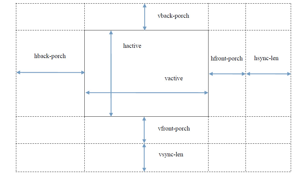
Time series attributes refer to the following figure:
Init Code
MIPI
The MIPI screen needs to send initialization instructions to make it work after it is powered up.
DTS
You can see the list of MIPI initialization instructions in kernel/arch/arm64/boot/dts/rockchip/rk3399-firefly-mipi.dts:
&dsi {
            status = "okay";
        ...
            panel-init-sequence = [
                05 20 01 29
                05 96 01 11
            ];

            panel-exit-sequence = [
                05 05 01 28
                05 78 01 10
            ];
        ...
};
The command format and instructions can be found in the following annexes:
Rockchip DRM Panel Porting Guide.pdf
Kernel
Send instructions to see the operation in the file kernel/drivers/gpu/drm/panel/panel-simple.c:
static int panel_simple_enable(struct drm_panel *panel)
{
    struct panel_simple *p = to_panel_simple(panel);
    int err;
    if (p->enabled)
        return 0;
    DBG("enter\n");
    if (p->on_cmds) {
        err = panel_simple_dsi_send_cmds(p, p->on_cmds);
        if (err)
            dev_err(p->dev, "failed to send on cmds\n");
    }
    if (p->desc && p->desc->delay.enable) {
        DBG("p->desc->delay.enable=%d\n", p->desc->delay.enable);
        msleep(p->desc->delay.enable);
    }
    if (p->backlight) {
        DBG("open backlight\n");
        p->backlight->props.power = FB_BLANK_UNBLANK;
        backlight_update_status(p->backlight);
    }
    p->enabled = true;
    return 0;
}
U-Boot
Send instructions to see the operation in the u-boot/drivers/video/rockchip-dw-mipi-dsi.c file:
static int rockchip_dw_mipi_dsi_enable(struct display_state *state)
{
    struct connector_state *conn_state = &state->conn_state;
    struct crtc_state *crtc_state = &state->crtc_state;
    const struct rockchip_connector *connector = conn_state->connector;
    const struct dw_mipi_dsi_plat_data *pdata = connector->data;
    struct dw_mipi_dsi *dsi = conn_state->private;
    u32 val;
    DBG("enter\n");
    dw_mipi_dsi_set_mode(dsi, DW_MIPI_DSI_VID_MODE);
    dsi_write(dsi, DSI_MODE_CFG, ENABLE_CMD_MODE);
    dw_mipi_dsi_set_mode(dsi, DW_MIPI_DSI_VID_MODE);
    if (!pdata->has_vop_sel)
        return 0;
    if (pdata->grf_switch_reg) {
        if (crtc_state->crtc_id)
            val = pdata->dsi0_en_bit | (pdata->dsi0_en_bit << 16);
        else
            val = pdata->dsi0_en_bit << 16;
        writel(val, RKIO_GRF_PHYS + pdata->grf_switch_reg);
    }
    debug("vop %s output to dsi0\n", (crtc_state->crtc_id) ? "LIT" : "BIG");
    //rockchip_dw_mipi_dsi_read_allregs(dsi);
    return 0;
}