6. DIN
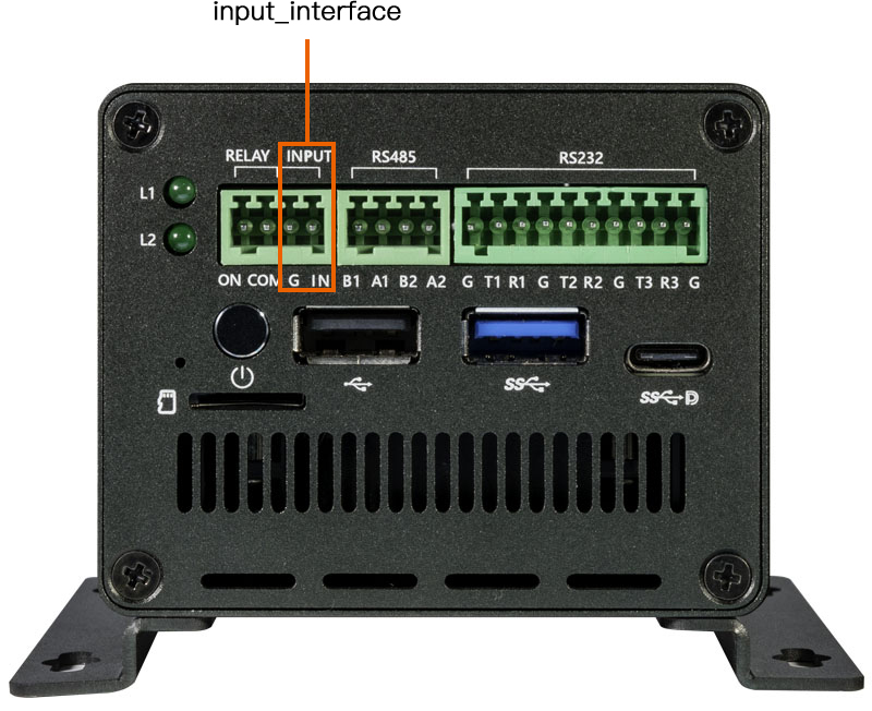
EC-R3588SPC supports an optocoupler isolation input, where IN corresponds to INPUT1 in the hardware schematic diagram and G corresponds to INPUT_COM in the hardware schematic diagram.
6.1. Interface Diagram
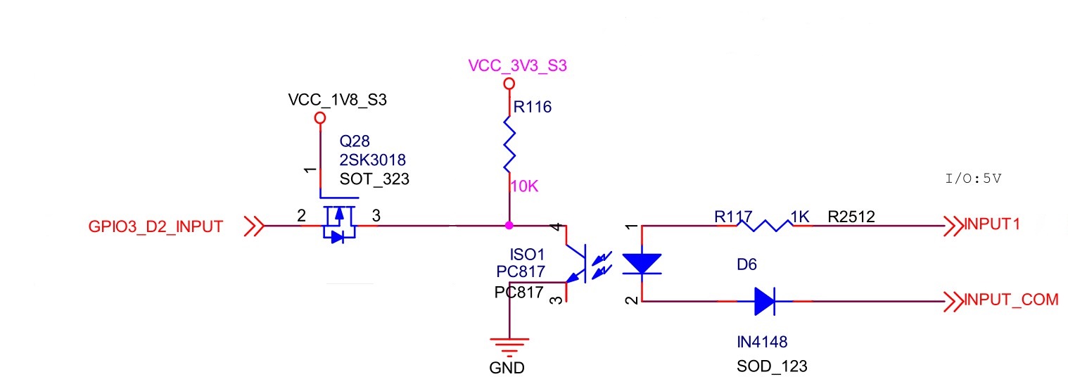
6.2. schematic diagram
6.3. Detect
The INPUT1 in the schematic corresponds to the IN for silk screen printing, and the INPUT_COM corresponds to G. When INPUT1(IN) and INPUT_COM(G) are conducting, GPIO3_D2_INPUT will detect a low level; When INPUT1(IN) and INPUT_COM(G) are disconnected, GPIO3_D2_INPUT will detect a high level.
Example 1: If ‘Input (IN)’ is connected to 5V, then it is to detect the input status of ‘Input-COM (G)’. When ‘Input-COM (G)’ is low, the main control detects that ‘GPIO3DD2-INPUT’ is low;
*Example 2: If you want to connect to 24V, you need to connect a resistor (with a resistance value between 3.9K and 4.7K) before connecting to ‘Input (IN)’ to prevent burning out the optocoupler isolation chip. The logic is consistent with Example 1;
Note: It is strongly recommended to use the solution of Example 1. If you have other configuration ideas, please configure ‘Input (IN)’ and ‘Input-COM (G)’ according to the actual circuit schematic to prevent burning the optocoupler
The Detect mode is as follows:
# get GPIO export
echo 122 > /sys/class/gpio/export
# set direction to input
echo in > /sys/class/gpio/gpio122/direction
# read value
cat /sys/class/gpio/gpio122/value