6. UART Usage
6.2. DTS Config
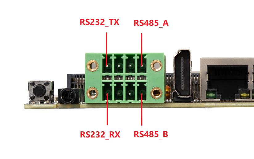
The board’s RS232 is from UART9 and RS485 is from UART6.
DTS file: `kernel/arch/arm64/boot/dts/rockchip/rk3588-firefly-aio-3588sjd4-ai.dtsi
&uart6 {
        pinctrl-0 = <&uart6m1_xfer>;
        status = "okay";
};

&uart9 {
        pinctrl-0 = <&uart9m2_xfer>;
        status = "okay";
};
So the corresponding nodes in system are:
RS232 :   /dev/ttyS9
RS485 :   /dev/ttyS6
6.3. Send and Receive
Pin GPIO1_A2 is used for RS485 direction control. Pull up this GPIO means RS485 is in send mode, pull down means RS485 is in receive mode.
User can use /sys/class/gpio sub-system to control GPIO.
All serial default baudrate is 9600, and 8 data bits, 1 stop bit, no flow control. User can use “echo” and “cat” command to simply test serials.