LCD
Introduction
The AIO-3399JD4 development board supports two LCD screen interfaces by default externally, one is LVDS and the other is EDP. The position of the interface on the board is as follows:
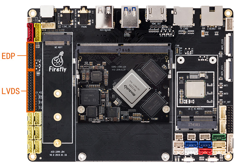
In addition, the board also supports MIPI screens, but it should be noted that MIPI and LVDS are multiplexed, and LVDS cannot be used after MIPI is used. Customers need to solder the MIPI interface by themselves, as shown in the figure below, and also need to remove the 3 rows of resistors in the red box:

LVDS screen
DTS configuration
Pin configuration
AIO-3399JD4 SDK has LVDS DSI DTS file: kernel/arch/arm64/boot/dts/rockchip/rk3399-firefly-aiojd4-lvds-HSX101H40C.dts, from this file we can see the following statement:
/ {
	model = "AIO-3399JD4 Board lvds HSX101H40C (Android)";
	compatible = "rockchip,android", "rockchip,rk3399-firefly-lvds", "rockchip,rk3399";
};

&backlight {
        status = "okay";
        pwms = <&pwm0 0 25000 1>;
        enable-gpios = <&gpio1 1 GPIO_ACTIVE_HIGH>;
        default-brightness-level = <200>;
        polarity = <1>;
        brightness-levels = </*
                          0   1   2   3   4   5   6   7
                          8   9  10  11  12  13  14  15
                         16  17  18  19  20  21  22  23
                         24  25  26  27  28  29  30  31
                         32  33  34  35*/36  37  38  39
                         40  41  42  43  44  45  46  47
                         48  49  50  51  52  53  54  55
                         56  57  58  59  60  61  62  63
                         64  65  66  67  68  69  70  71
                         72  73  74  75  76  77  78  79
                         80  81  82  83  84  85  86  87
                         88  89  90  91  92  93  94  95
                         96  97  98  99 100 101 102 103
                        104 105 106 107 108 109 110 111
                        112 113 114 115 116 117 118 119
                        120 121 122 123 124 125 126 127
                        128 129 130 131 132 133 134 135
                        136 137 138 139 140 141 142 143
                        144 145 146 147 148 149 150 151
                        152 153 154 155 156 157 158 159
                        160 161 162 163 164 165 166 167
                        168 169 170 171 172 173 174 175
                        176 177 178 179 180 181 182 183
                        184 185 186 187 188 189 190 191
                        192 193 194 195 196 197 198 199
                        200 201 202 203 204 205 206 207
                        208 209 210 211 212 213 214 215
                        216 217 218 219 220 221 222 223
                        224 225 226 227 228 229 230 231
                        232 233 234 235 236 237 238 239
                        240 241 242 243 244 245 246 247
                        248 249 250 251 252 253 254 255>;
};

&dsi {
        status = "okay";
        dsi_panel: panel {
                compatible ="simple-panel-dsi";
                reg = <0>;
                //ddc-i2c-bu
                //power-supply = <&vcc_lcd>;
                //pinctrl-0 = <&lcd_panel_reset &lcd_panel_enable>;
                backlight = <&backlight>;
                /*
                enable-gpios = <&gpio1 1 GPIO_ACTIVE_LOW>;
                reset-gpios = <&gpio4 29 GPIO_ACTIVE_LOW>;
                */
                dsi,flags = <(MIPI_DSI_MODE_VIDEO | MIPI_DSI_MODE_VIDEO_BURST | MIPI_DSI_MODE_LPM | MIPI_DSI_MODE_EOT_PACKET)>;
                dsi,format = <MIPI_DSI_FMT_RGB888>;
                //bus-format = <MEDIA_BUS_FMT_RGB666_1X18>;
                dsi,lvds-force-clk = <800>; // 800/2/3 ~= 65Mhz
                dsi,lanes = <4>;

                dsi,channel = <0>;

                enable-delay-ms = <35>;
                prepare-delay-ms = <6>;

                unprepare-delay-ms = <0>;
                disable-delay-ms = <20>;

                size,width = <120>;
                size,height = <170>;

                status = "okay";

                panel-init-sequence = [
                            29 02 06 3C 01 09 00 07 00
                            29 02 06 14 01 06 00 00 00
                            29 02 06 64 01 0B 00 00 00
                            29 02 06 68 01 0B 00 00 00
                            29 02 06 6C 01 0B 00 00 00
                            29 02 06 70 01 0B 00 00 00
                            29 02 06 34 01 1F 00 00 00
                            29 02 06 10 02 1F 00 00 00
                            29 02 06 04 01 01 00 00 00
                            29 02 06 04 02 01 00 00 00
                            29 02 06 50 04 20 01 F0 03
                            29 02 06 54 04 19 00 5A 00                       //5A
                            29 02 06 58 04 20 03 24 00
                            29 02 06 5C 04 0A 00 19 00
                            29 02 06 60 04 00 05 0A 00
                            29 02 06 64 04 01 00 00 00
                            29 02 06 A0 04 06 80 44 00

                            29 02 06 A0 04 06 80 04 00
                            29 02 06 04 05 04 00 00 00
                            29 02 06 80 04 00 01 02 03
                            29 02 06 84 04 04 07 05 08
                            29 02 06 88 04 09 0A 0E 0F
                            29 02 06 8C 04 0B 0C 0D 10
                            29 02 06 90 04 16 17 11 12
                            29 02 06 94 04 13 14 15 1B
                            29 02 06 98 04 18 19 1A 06

                            29 02 06 9C 04 31 04 00 00
                ];
                panel-exit-sequence = [
                        05 05 01 28
                        05 78 01 10
                ];

                power_ctr: power_ctr {
                        rockchip,debug = <0>;
                        power_enable = <1>;
	                    bl_en:bl_en {
                                gpios = <&gpio0 1 GPIO_ACTIVE_HIGH>;
                                pinctrl-names = "default";
                                pinctrl-0 = <&lcd_panel_bl_en>;
                                rockchip,delay = <0>;
	                    };
	                    lcd_en:lcd_en {
                                gpios = <&gpio1 4 GPIO_ACTIVE_HIGH>;
                                pinctrl-names = "default";
                                pinctrl-0 = <&lcd_panel_lcd_en>;
                                rockchip,delay = <10>;
	                    };
                        lcd_pwr_en: lcd-pwr-en {
                                gpios = <&gpio0 12 GPIO_ACTIVE_HIGH>;
                                pinctrl-names = "default";
                                pinctrl-0 = <&lcd_panel_pwr_en>;
                                rockchip,delay = <10>;
                        };

                        lcd_rst: lcd-rst {
                                gpios = <&gpio1 13 GPIO_ACTIVE_HIGH>;
                                pinctrl-names = "default";
                                pinctrl-0 = <&lcd_panel_reset>;
                                rockchip,delay = <6>;
                        };
                };

                disp_timings: display-timings {
                        native-mode = <&timing0>;
                        timing0: timing0 {
                                clock-frequency = <166000000>; //166000000 @50
                                hactive = <800>;
                                vactive = <1280>;
                                hsync-len = <10>;   //20, 50
                                hback-porch = <100>; //50, 56
                                hfront-porch = <1580>;//50, 30 //1580
                                vsync-len = <10>;
                                vback-porch = <25>;
                                vfront-porch = <10>;
                                hsync-active = <0>;
                                vsync-active = <0>;
                                de-active = <0>;
                                pixelclk-active = <0>;
                        };
                };
        };
};
The power control pins of the LCD are defined here:
bl_en:(GPIO0_A1)GPIO_ACTIVE_HIGH
lcd_en:(GPIO1_A4)GPIO_ACTIVE_HIGH
lcd_pwr_en:(GPIO0_B4)GPIO_ACTIVE_HIGH
lcd_rst:(GPIO1_B5)GPIO_ACTIVE_HIGH
All are active at high level. Please refer to the section “GPIO Usage” for specific pin configuration.
LVDS configuration backlight
The AIO-3399JD4 development board has an external backlight interface to control the screen backlight, as shown in the following figure:
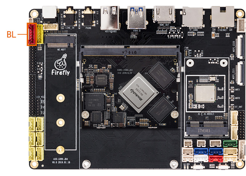
The backlight information is configured in the DTS file: kernel/arch/arm64/boot/dts/rockchip/rk3399-firefly-core.dtsi, as follows:
/ {
    compatible = "rockchip,rk3399-firefly-core", "rockchip,rk3399";

    backlight: backlight {
        status = "disabled";
        compatible = "pwm-backlight";
        pwms = <&pwm0 0 25000 0>;
        brightness-levels = <
              0   1   2   3   4   5   6   7
              8   9  10  11  12  13  14  15
             16  17  18  19  20  21  22  23
             24  25  26  27  28  29  30  31
             32  33  34  35  36  37  38  39
             40  41  42  43  44  45  46  47
             48  49  50  51  52  53  54  55
             56  57  58  59  60  61  62  63
             64  65  66  67  68  69  70  71
             72  73  74  75  76  77  78  79
             80  81  82  83  84  85  86  87
             88  89  90  91  92  93  94  95
             96  97  98  99 100 101 102 103
            104 105 106 107 108 109 110 111
            112 113 114 115 116 117 118 119
            120 121 122 123 124 125 126 127
            128 129 130 131 132 133 134 135
            136 137 138 139 140 141 142 143
            144 145 146 147 148 149 150 151
            152 153 154 155 156 157 158 159
            160 161 162 163 164 165 166 167
            168 169 170 171 172 173 174 175
            176 177 178 179 180 181 182 183
            184 185 186 187 188 189 190 191
            192 193 194 195 196 197 198 199
            200 201 202 203 204 205 206 207
            208 209 210 211 212 213 214 215
            216 217 218 219 220 221 222 223
            224 225 226 227 228 229 230 231
            232 233 234 235 236 237 238 239
            240 241 242 243 244 245 246 247
            248 249 250 251 252 253 254 255>;
        default-brightness-level = <200>;
};
pwms attribute: Configure PWM. In the example, pwm0 is used by default, and 25000ns is the period (40 KHz). LVDS needs to add backlight power control pin. You can see the following statement in kernel/arch/arm64/boot/dts/rockchip/rk3399-firefly-aiojd4-lvds-HSX101H40C.dts:
&backlight {
    status = "okay";
    enable-gpios = <&gpio1 1 GPIO_ACTIVE_HIGH>;
    brightness-levels = < 150 151
    152 153 154 155 156 157 158 159
    160 161 162 163 164 165 166 167
    168 169 170 171 172 173 174 175
    176 177 178 179 180 181 182 183
    184 185 186 187 188 189 190 191
    192 193 194 195 196 197 198 199
    200 201 202 203 204 205 206 207
    208 209 210 211 212 213 214 215
    216 217 218 219 220 221 222 223
    224 225 226 227 228 229 230 231
    232 233 234 235 236 237 238 239
    240 241 242 243 244 245 246 247
    248 249 250 251 252 253 254 255>;
};
Therefore, the DTS file needs to be modified when using it.
Brightness-levels property: Configure the backlight brightness array, the maximum value is 255, configure the dark area and the bright area, and adjust the ratio of the bright area array to 255. For example, in the example, the dark area is 255-221, and the bright area is 220-0. default-brightness-level attribute: the default backlight brightness at startup, the range is 0-255. For details, please refer to the documentation in the kernel: kernel/Documentation/devicetree/bindings/leds/backlight/pwm-backlight.txt
Configure display timing
Unlike the EDP screen, the Timing of the LVDS screen is written in the DTS file. The following statement can be seen in kernel/arch/arm64/boot/dts/rockchip/rk3399-firefly-aiojd4-lvds-HSX101H40C.dts:
disp_timings: display-timings {
                        native-mode = <&timing0>;
                        timing0: timing0 {
                                clock-frequency = <166000000>; //166000000 @50
                                hactive = <800>;
                                vactive = <1280>;
                                hsync-len = <10>;   //20, 50
                                hback-porch = <100>; //50, 56
                                hfront-porch = <1580>;//50, 30 //1580
                                vsync-len = <10>;
                                vback-porch = <25>;
                                vfront-porch = <10>;
                                hsync-active = <0>;
                                vsync-active = <0>;
                                de-active = <0>;
                                pixelclk-active = <0>;
                        };
                };
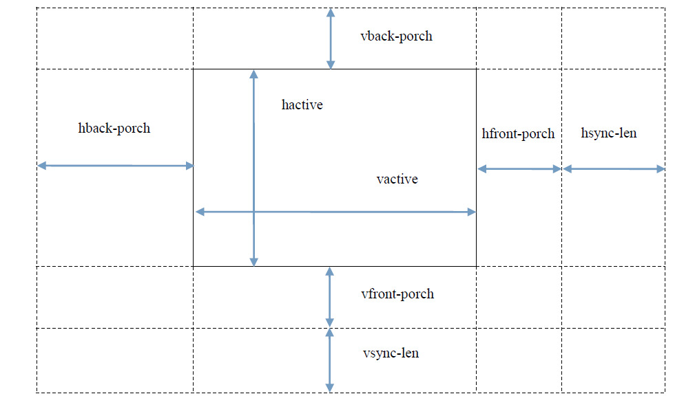
Refer to the figure below for timing attributes:
Init Code
After the lvds screen is powered up, an initialization command needs to be sent to make it work. The initialization command needs to be generated by the following tool documents, download TC358764_5_774_5XBG_DSI-LVDS_Tv11p_nm_1280x800.xls
Calculate LVDS panel-init-sequence
Take 1280x800 single LVDS as an example:
Open TC358764_5_774_5XBG_DSI-LVDS_Tv11p_nm_1280x800.xls

Select “timing parameters_sync_event” on the page and fill in the LVDS timing yellow cell according to the sequence of LVDS screen. Generally, only the following cell need to be filled in.
HPW / HBPR / HDISPR / HFPR corresponding hsync-len / hback-porch / hactive / hfront-porch
VPW / VBPR / VDISPR / VFPR corresponding vhsync-len / vback-porch / vactive / vfront-porch
After LVDS timing is filled in, it is also necessary to configure general parameters
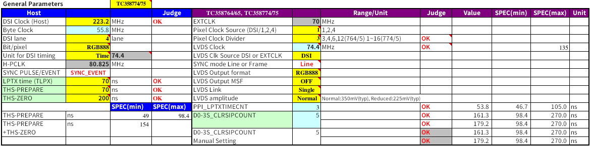
1.Confirm LVDS link and LVDS output format according to LVDS screen specification and select screen parameters.
2.Calculate LVDS clock (the blue cell cannot be written, which needs to be calculated automatically by the Yellow cell), and fill in DSI Clock(HOST), Pixel Clock Source, Pixel Clock Divider。The calculation formula is as follows:DSI Clock/Pixel Clock Source/Pixel Clock Divider=LVDS Clock
Fill in the above yellow cell and basically complete the configuration. Next, select “source” on the page to see the converted comment
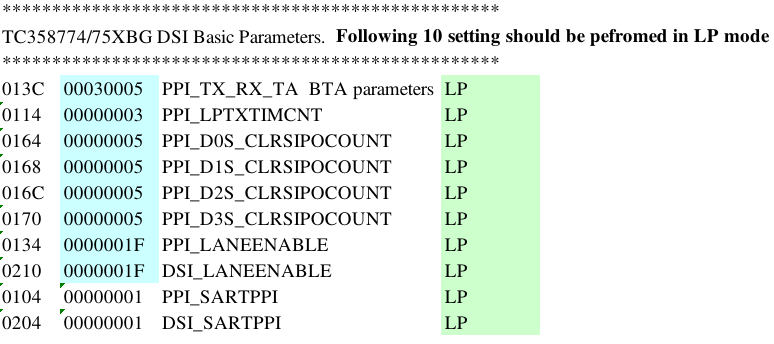 Take the above example “013C 00030005”, Mipi command should be “29 02 06 3C 01 05 00 03 00”
29 : packet ID
02 : 2ms delay
06 : 6 bytes
3C 01 : address = 0x013C
00 03 00 05 : data=0x05000300 Write all the addresses of the page source into the data to complete the panel init sequence.
You can see the initialization instruction list of lvds in kernel/arch/arm64/boot/dts/rockchip/rk3399-firefly-aiojd4-lvds-HSX101H40C.dts:
&dsi {
   status = "okay";
        ...
  panel-init-sequence = [
  29 00 06 3C 01 09 00 07 00
  29 00 06 14 01 06 00 00 00
  29 00 06 64 01 0B 00 00 00
  29 00 06 68 01 0B 00 00 00
  29 00 06 6C 01 0B 00 00 00
  29 00 06 70 01 0B 00 00 00
  29 00 06 34 01 1F 00 00 00
  29 00 06 10 02 1F 00 00 00
  29 00 06 04 01 01 00 00 00
  29 00 06 04 02 01 00 00 00
  29 00 06 50 04 20 01 F0 03
  29 00 06 54 04 32 00 B4 00
  29 00 06 58 04 80 07 48 00
  29 00 06 5C 04 0A 00 19 00
  29 00 06 60 04 38 04 0A 00
  29 00 06 64 04 01 00 00 00
  29 01 06 A0 04 06 80 44 00
  29 00 06 A0 04 06 80 04 00
  29 00 06 04 05 04 00 00 00
  29 00 06 80 04 00 01 02 03
  29 00 06 84 04 04 07 05 08
  29 00 06 88 04 09 0A 0E 0F
  29 00 06 8C 04 0B 0C 0D 10
  29 00 06 90 04 16 17 11 12
  29 00 06 94 04 13 14 15 1B
  29 00 06 98 04 18 19 1A 06
  29 02 06 9C 04 33 04 00 00
  ];
  panel-exit-sequence = [
                        05 05 01 28
                        05 78 01 10
  ];
        ...
};
For command format and description, please refer to the following attachments: Rockchip DRM Panel Porting Guide.pdf
kernel Send the command to see the operation in the kernel/drivers/gpu/drm/panel/panel-simple.c file:
static int panel_simple_enable(struct drm_panel *panel)
{
    struct panel_simple *p = to_panel_simple(panel);
    int err;
    if (p->enabled)
        return 0;
    DBG("enter\n");
    if (p->on_cmds) {
        err = panel_simple_dsi_send_cmds(p, p->on_cmds);
        if (err)
            dev_err(p->dev, "failed to send on cmds\n");
    }
    if (p->desc && p->desc->delay.enable) {
        DBG("p->desc->delay.enable=%d\n", p->desc->delay.enable);
        msleep(p->desc->delay.enable);
    }
    if (p->backlight) {
        DBG("open backlight\n");
        p->backlight->props.power = FB_BLANK_UNBLANK;
        backlight_update_status(p->backlight);
    }
    p->enabled = true;
    return 0;
}
u-boot Send the command to see the operation in the u-boot/drivers/video/rockchip-dw-mipi-dsi.c file:
static int rockchip_dw_mipi_dsi_enable(struct display_state *state)
{
    struct connector_state *conn_state = &state->conn_state;
    struct crtc_state *crtc_state = &state->crtc_state;
    const struct rockchip_connector *connector = conn_state->connector;
    const struct dw_mipi_dsi_plat_data *pdata = connector->data;
    struct dw_mipi_dsi *dsi = conn_state->private;
    u32 val;
    DBG("enter\n");
    dw_mipi_dsi_set_mode(dsi, DW_MIPI_DSI_VID_MODE);
    dsi_write(dsi, DSI_MODE_CFG, ENABLE_CMD_MODE);
    dw_mipi_dsi_set_mode(dsi, DW_MIPI_DSI_VID_MODE);
    if (!pdata->has_vop_sel)
        return 0;
    if (pdata->grf_switch_reg) {
        if (crtc_state->crtc_id)
            val = pdata->dsi0_en_bit | (pdata->dsi0_en_bit << 16);
        else
            val = pdata->dsi0_en_bit << 16;
        writel(val, RKIO_GRF_PHYS + pdata->grf_switch_reg);
    }
    debug("vop %s output to dsi0\n", (crtc_state->crtc_id) ? "LIT" : "BIG");
    //rockchip_dw_mipi_dsi_read_allregs(dsi);
    return 0;
}
FAQs
1. does the screen shake or flash?
Check whether the screen parameters exceed the limited cycle of the screen specification, and check the screen clock size. “Timing parameters_sync_event” all parameter changes must be adjusted synchronously with comment.
2. Abnormal color display
Try to adjust color mapping or LVDS timing synchronously.
**Note * *: the page “how to use” has detailed steps. For other parameter descriptions, please refer to the document “page” menu.
EDP screen
DTS configuration
Pin configuration
The SDK of AIO-3399JD4 has the DTS file of EDP DSI: kernel/arch/arm64/boot/dts/rockchip/rk3399-firefly-aiojd4-edp.dts, from which we can see the following statement:
  edp_panel: edp-panel {
		/* config 2 */
		compatible = "lg,lp079qx1-sp0v";
		/* config 3 */
		//compatible = "simple-panel";
		bus-format = <MEDIA_BUS_FMT_RGB666_1X18>;

		backlight = <&backlight>;

		ports {
			panel_in_edp: endpoint {
				remote-endpoint = <&edp_out_panel>;
			};
		};

		power_ctr: power_ctr {
		power_enable = <1>;
               rockchip,debug = <0>;
               lcd_en: lcd-en {
                       gpios = <&gpio1 4 GPIO_ACTIVE_HIGH>;
					   pinctrl-names = "default";
					   pinctrl-0 = <&lcd_panel_enable>;
                       rockchip,delay = <20>;
               };
               lcd_pwr_en: lcd-pwr-en {
                       gpios = <&gpio0 1 GPIO_ACTIVE_HIGH>;
                       pinctrl-names = "default";
                       pinctrl-0 = <&lcd_panel_pwr_en>;
                       rockchip,delay = <10>;
               };
       };
};
···
&pinctrl {
	lcd-panel {
		lcd_panel_enable: lcd-panel-enable {
			rockchip,pins = <1 4 RK_FUNC_GPIO &pcfg_pull_up>;
		};
        lcd_panel_pwr_en: lcd-panel-pwr-en {
            rockchip,pins = <0 1 RK_FUNC_GPIO &pcfg_pull_up>;
        };
	};
};
The power control pins of the LCD are defined here:
lcd_en:(GPIO1_A4)GPIO_ACTIVE_HIGH
lcd_pwr_en:(GPIO0_A1)GPIO_ACTIVE_HIGH
All are active at high level. Please refer to the section “GPIO Usage” for specific pin configuration.
EDP configuration backlight
Because the backlight interface is common, you can refer to the above-mentioned LVDS configuration method.
EDP configuration display timing
The kernel writes Timing in panel-simple.c and directly matches with short strings. There are the following statements in the drivers/gpu/drm/panel/panel-simple.c file
static const struct drm_display_mode lg_lp079qx1_sp0v_mode = {
  .clock = 200000,
  .hdisplay = 1536,
  .hsync_start = 1536 + 12,
  .hsync_end = 1536 + 12 + 16,
  .htotal = 1536 + 12 + 16 + 48,
  .vdisplay = 2048,
  .vsync_start = 2048 + 8,
  .vsync_end = 2048 + 8 + 4,
  .vtotal = 2048 + 8 + 4 + 8,
  .vrefresh = 60,
  .flags = DRM_MODE_FLAG_NVSYNC | DRM_MODE_FLAG_NHSYNC,
};

static const struct panel_desc lg_lp097qx1_spa1 = {
  .modes = &lg_lp097qx1_spa1_mode,
  .num_modes = 1,
  .size = {
    .width = 320,
    .height = 187,
  },
};

... ...

   static const struct of_device_id platform_of_match[] = {
  {
    .compatible = "simple-panel",
    .data = NULL,
  },{

  }, {
    .compatible = "lg,lp079qx1-sp0v",
    .data = &lg_lp079qx1_sp0v,
  }, {

  }, {
    /* sentinel */
  }
};
MODULE_DEVICE_TABLE(of, platform_of_match); The timing parameters are configured in the structure lg_lp079qx1_sp0v_mode.
U-boot
Write Timing in rockchip_panel.c and directly match it with a short string. There are the following statements in the drivers/video/rockchip_panel.c file:
static const struct drm_display_mode lg_lp079qx1_sp0v_mode = {
  .clock = 200000,
  .hdisplay = 1536,
  .hsync_start = 1536 + 12,
  .hsync_end = 1536 + 12 + 16,
  .htotal = 1536 + 12 + 16 + 48,
  .vdisplay = 2048,
  .vsync_start = 2048 + 8,
  .vsync_end = 2048 + 8 + 4,
  .vtotal = 2048 + 8 + 4 + 8,
  .vrefresh = 60,
  .flags = DRM_MODE_FLAG_NVSYNC | DRM_MODE_FLAG_NHSYNC,
};
static const struct rockchip_panel g_panel[] = {
  {
    .compatible = "lg,lp079qx1-sp0v",
    .mode = &lg_lp079qx1_sp0v_mode,
  }, {
    .compatible = "auo,b125han03",
    .mode = &auo_b125han03_mode,
  },
};
The timing parameters are configured in the structure lg_lp079qx1_sp0v_mode.
MIPI screen
After customers add the mipi hardware interface according to their needs, configure the Timing dts file of the MIPI screen. You can see the following statement in kernel/arch/arm64/boot/dts/rockchip/rk3399-firefly-aiojd4-mipi.dts:
disp_timings: display-timings {
    native-mode = <&timing0>;
    timing0: timing0 {
         clock-frequency = <80000000>;
         hactive = <768>;
         vactive = <1024>;
         hsync-len = <20>;   //20, 50
         hback-porch = <130>; //50, 56
         hfront-porch = <150>;//50, 30
         vsync-len = <40>;
         vback-porch = <130>;
         vfront-porch = <136>;
         hsync-active = <0>;
         vsync-active = <0>;
         de-active = <0>;
         pixelclk-active = <0>;
           };
    }
}
Kernel In kernel/drivers/gpu/drm/panel/panel-simple.c, you can see that the function to get the timing sequence is initialized in the initialization function panel_simple_probe.
static int panel_simple_probe(struct device *dev, const struct panel_desc *desc){
···
 panel->base.funcs = &panel_simple_funcs;
···
}
This function is also defined in kernel/drivers/gpu/drm/panel/panel-simple.c:
static int panel_simple_get_timings(struct drm_panel *panel,unsigned int num_timings,struct display_timing *timings)
{
    struct panel_simple *p = to_panel_simple(panel);
    unsigned int i;
    if (!p->desc)
        return 0;

    if (p->desc->num_timings < num_timings)
        num_timings = p->desc->num_timings;

    if (timings)
        for (i = 0; i < num_timings; i++)
        timings[i] = p->desc->timings[i];
    return p->desc->num_timings;
}
After the mipi screen is powered on, you need to send an initialization command to make it work. You can see the mipi initialization command list in kernel/arch/arm64/boot/dts/rockchip/rk3399-firefly-mipi.dts:
&mipi_dsi {
            status = "okay";
        ...
            panel-init-sequence = [
                05 20 01 29
                05 96 01 11
            ];

            panel-exit-sequence = [
                05 05 01 28
                05 78 01 10
            ];
        ...
};
For command format and description, please refer to the following attachments: Rockchip DRM Panel Porting Guide.pdf
Send the command to see the operation in the kernel/drivers/gpu/drm/panel/panel-simple.c file:
static int panel_simple_enable(struct drm_panel *panel)
{
    struct panel_simple *p = to_panel_simple(panel);
    int err;
    if (p->enabled)
        return 0;
    DBG("enter\n");
    if (p->on_cmds) {
        err = panel_simple_dsi_send_cmds(p, p->on_cmds);
        if (err)
            dev_err(p->dev, "failed to send on cmds\n");
    }
    if (p->desc && p->desc->delay.enable) {
        DBG("p->desc->delay.enable=%d\n", p->desc->delay.enable);
        msleep(p->desc->delay.enable);
    }
    if (p->backlight) {
        DBG("open backlight\n");
        p->backlight->props.power = FB_BLANK_UNBLANK;
        backlight_update_status(p->backlight);
    }
    p->enabled = true;
    return 0;
}
U-boot
Send the command to see the operation in the u-boot/drivers/video/rockchip-dw-mipi-dsi.c file:
static int rockchip_dw_mipi_dsi_enable(struct display_state *state)
{
    struct connector_state *conn_state = &state->conn_state;
    struct crtc_state *crtc_state = &state->crtc_state;
    const struct rockchip_connector *connector = conn_state->connector;
    const struct dw_mipi_dsi_plat_data *pdata = connector->data;
    struct dw_mipi_dsi *dsi = conn_state->private;
    u32 val;
    DBG("enter\n");
    dw_mipi_dsi_set_mode(dsi, DW_MIPI_DSI_VID_MODE);
    dsi_write(dsi, DSI_MODE_CFG, ENABLE_CMD_MODE);
    dw_mipi_dsi_set_mode(dsi, DW_MIPI_DSI_VID_MODE);
    if (!pdata->has_vop_sel)
        return 0;
    if (pdata->grf_switch_reg) {
        if (crtc_state->crtc_id)
            val = pdata->dsi0_en_bit | (pdata->dsi0_en_bit << 16);
        else
            val = pdata->dsi0_en_bit << 16;
        writel(val, RKIO_GRF_PHYS + pdata->grf_switch_reg);
    }
    debug("vop %s output to dsi0\n", (crtc_state->crtc_id) ? "LIT" : "BIG");
    //rockchip_dw_mipi_dsi_read_allregs(dsi);
    return 0;
}