RKMedia
Module Introduction
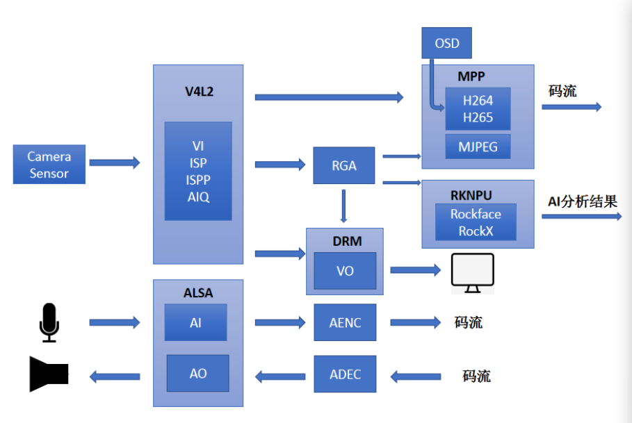
RKMedia is a set of API interfaces that integrate and encapsulate all media resource calls in RV1126/RV1109. It can greatly reduce the development cost of users who just contact RV1126/RV1109 chip platform, and all media resources on SoC can be called quickly and simply with a small amount of code. At the same time, RKMedia also provides joint call DEMO of hardware resources other than media resources, such as: RKAIQ, RKNN, RTSP and so on. The core idea of RKMedia is to separate each hardware resource into a module, and the input and output ends of the module are open to control the flow from one module to another module by binding. Each module is described here.
Video
VI
VIis a video input module, which can be understood as a camera acquisition module. It should be noted thatVIneeds the support ofRKAIQ, andRKAIQneeds to be initialized in advance before usingVI. Detailed initialization steps can be viewed in Example.VIchannel properties set
MPP_CHN_S stViChn;			# Define the module device channel structure
stViChn.enModId = RK_ID_VI;	# Module number is RK_ID_VI
Stvichn.s32ChnId 				# Sets the VI channel number

VI_CHN_ATTR_S vi_chn_attr;	#Define the VI channel attribute structure pointer
vi_chn_attr.u32BufCnt			# VI captures the video buffer count
vi_chn_attr.u32Width			# video width
vi_chn_attr.u32Height			# video height
vi_chn_attr.enWorkMode		# VI channel working mode
vi_chn_attr.pcVideoNode		# video node path
vi_chn_attr.enPixFmt			# video format
Set the
VIchannel properties
# Function Definition:
RK_MPI_VI_SetChnAttr(VI_PIPE ViPipe, VI_CHN ViChn, const VI_CHN_ATTR_S *pstChnAttr);
# ViPipe is the pipeline number of VI; Vichn is the VI channel number; pstChnAttr is a pointer to the VI channel attribute structure.
# Examples of use:
RK_MPI_VI_SetChnAttr(vi_pipe, stViChn.s32ChnId, &vi_chn_attr);
Enable the
VIchannel
# Function Definition:
RK_S32 RK_MPI_VI_EnableChn(VI_PIPE ViPipe, VI_CHN ViChn);
# ViPipe is the pipeline number of VI; Vichn is the VI channel number.
# Examples of use:
RK_MPI_VI_EnableChn(vi_pipe, stViChn.s32ChnId);
VP
One video input and four outputs
VPuses theISPPmodule to realize one video from rkispp_input_image node corresponding to video input, four videos from rkispp_m_bypass , rkispp_scale0 , rkispp_scale1 , rkispp_scale2 nodes corresponding to video output, node information can be viewed through the following commands:
media-ctl -p -d /dev/media*
Use VP to complete the video input from the rkispp_input_image node corresponding to the video, and use VI to complete the video output from the rkispp_m_bypass , rkispp_scale0 , rkispp_scale1 , rkispp_scale2 nodes corresponding to the video, you can achieve one video input and four output. rkispp_scale0 , rkispp_scale1 , rkispp_scale2 can implement
scaling, which can replace the scaling function of RGA, and can relieve the processing pressure of RGA hardware for DVR and other related products.To use the VP function, you need to configure the rkispp_vir2 node in the kernel first (configured by default), for example:
&rkispp_vir2 {
       status = "okay";
};
To use the VP function, you need to configure the corresponding media node first, for example:
media-ctl -d /dev/media3 -l '"rkispp_input_image":0->"rkispp-subdev":0[1]'
media-ctl -d /dev/media3 --set-v4l2 '"rkisppsubdev":0[fmt:YUYV8_2X8/1920x1080]'
media-ctl -d /dev/media3 --set-v4l2 '"rkisppsubdev":2[fmt:YUYV8_2X8/1920x1080]'
Note: After the configuration is completed, you need to open 4 output nodes (1 to 4 can be opened), and finally open the input nodes. Data for input nodes can come from other VIs, RGAs, and so on. For specific examples, please refer to sdk/external/rkmedia/examples/rkmedia_vi_vp_vo_test.c in the SDK.
VDEC
VDECmodule, namely video decoding module. This module supportsmulti-channel real-time decoding, andeach channel decoding is independent, and supportsH264/H265/MJPEG/JPEGdecoding.Decode channel property Settings
MPP_CHN_S stVdecChn;					# Define the module device channel structure
stVdecChn.enModId = RK_ID_VDEC;		# Module number is RK_ID_VDEC
stVdecChn.s32ChnId						# Sets the decoding channel number

VDEC_CHN_ATTR_S stVdecAttr;			# Define the decoding channel attribute structure
stVdecAttr.enCodecType					# Decoding format
stVdecAttr.enMode							# Decodes input mode and supports frames/streams
stVdecAttr.enDecodecMode				# Decoding mode, support hardware or software decoding
Create the
VDECdecoding channel
# Function Definition:
RK_S32 RK_MPI_VDEC_CreateChn(VDEC_CHN VdChn, const VDEC_CHN_ATTR_S *pstAttr);
# VdChn is the decoding channel number; pstAttr is a pointer to the decoded channel property.
# Examples of use:
RK_MPI_VDEC_CreateChn(stVdecChn.s32ChnId, &stVdecAttr);
RGA
RGAmodule is used forcropping,format conversion,scaling,rotation,image overlayand so on of2Dimages.The use of
RGAprocessing can greatly reduce the CPU burden, and speed up the image processing speed. (Refer: 1080p image format conversion. RGA Time: 7ms, OpenCV Time: 50ms).The
RGAchannel inrkmediaonly supportsclip,format conversion,zoomandrotation, whileimage overlayrequires a separate call to librga.so library. Seerockchip_developer_guide_linux_rga_cn.pdfRGAchannel properties set
MPP_CHN_S stRgaChn;				# Define the module device channel structure
stRgaChn.enModId = RK_ID_RGA;		# Module number is RK_ID_RGA
Strgachn.s32ChnId						# Sets the decoding channel number

RGA_ATTR_S stRgaAttr;				# Define the RGA attribute structure
stRgaAttr.bEnBufPool					# Enable buffer pool
stRgaAttr.u16BufPoolCnt				# Buffer pool count
stRgaAttr.u16Rotaion					# Rotate values in the range 0,90,180,270
stRgaAttr.stImgIn.u32X					# RGA channel enters the X-axis coordinates of the image
stRgaAttr.stImgIn.u32Y					# RGA channel enters the Y-axis coordinates of the image
stRgaAttr.stImgIn.imgType				# RGA channel input image format
stRgaAttr.stImgIn.u32Width			# Input image width
stRgaAttr.stImgIn.u32Height			# Input image height
stRgaAttr.stImgIn.u32HorStride		# Enter the virtual width of the image
stRgaAttr.stImgIn.u32VirStride			# Enter the virtual height of the image
stRgaAttr.stImgOut.u32X				# RGA channel outputs the X-axis coordinates of the image
stRgaAttr.stImgOut.u32Y				# RGA channel outputs the Y-axis coordinates of the image
stRgaAttr.stImgOut.imgType			# The RGA channel outputs the image format
stRgaAttr.stImgOut.u32Width			# The width of the output image
stRgaAttr.stImgOut.u32Height			# The height of the output image
stRgaAttr.stImgOut.u32HorStride		# Output image virtual width
stRgaAttr.stImgOut.u32VirStride		# Output image virtual height
Create the
RGAchannel
# Function Definition:
RK_S32 RK_MPI_RGA_CreateChn(RGA_CHN RgaChn, RGA_ATTR_S *pstRgaAttr);
# RgaChn is the RGA channel number; pstAttr is a pointer to an RGA channel property.
# Examples of use:
RK_MPI_RGA_CreateChn(stRgaChn.s32ChnId, &stRgaAttr);
stride width, usually the same as buffer_width. If u32VirWidth is greater than buffer width, align 16 must be satisfied.
The 16 alignment of variables can be set using the CELING_2_POWER function. Such as:
# Define the CELING_2_POWER macro
#define CELING_2_POWER(x,a) (((x) + ((a)-1)) & (~((a) - 1)))
# Use the CELING_2_POWER macro
stRgaAttr.stImgOut.u32VirStride = CELING_2_POWER(u32Height,16);
VO
VOmodule is used for video output management.VOmodule is the package ofDRM/KMSand supportsmulti-vopandmulti-graphic display.
MPP_CHN_S VoChn;						# Define the module device channel structure
VO_CHN_ATTR_S stVoAttr = {0};			# Define the video output attribute structure and initialize it to 0
memset(&stVoAttr, 0, sizeof(stVoAttr));

stVoAttr.pcDevNode = "/dev/dri/card0";	# Set the output device node to /dev/dri/card0
stVoAttr.emPlaneType						# Video output layer type
stVoAttr.enImgType						# Enter the image format
stVoAttr.u16Zpos							# Output the layer's Z-axis height
stVoAttr.u32Width							# Video output width
stVoAttr.u32Height							# Video output height
stVoAttr.stImgRect.s32X					# Video input the X-axis coordinates of the image region
stVoAttr.stImgRect.s32Y					# Video input the Y-axis coordinates of the image region
stVoAttr.stImgRect.u32Width				# The width of the input image region
stVoAttr.stImgRect.u32Height				# The height of the input image region
stVoAttr.stDispRect.s32X					# Displays the starting x-coordinate of the region
stVoAttr.stDispRect.s32Y					# Displays the starting Y-coordinate of the region
stVoAttr.stDispRect.u32Width				# The width of the display area
stVoAttr.stDispRect.u32Height				# The height of the display area

VoChn.enModId = RK_ID_VO;				# Module number is RK_ID_VO
Vochn.s32DevId							# Module device number
Vochn.s32ChnId							# Module channel number
Create a
VOchannel
# Function Definition:
RK_S32 RK_MPI_VO_CreateChn(VO_CHN VoChn, const VO_CHN_ATTR_S *pstAttr);
# VoChn is the VO channel number ; pstAttr is a pointer to a VO channel property.
# Examples of use:
RK_MPI_VO_CreateChn(VoChn.s32ChnId, &stVoAttr);
VENC
VENCmodule, namely video coding module. This module supportsmulti-channel real-time encoding, andeach encoding is independent, encoding protocol and encoding profile can be different. At the same time, the scheduling Region module overlapped and occluded the encoded image content. SupportH264/H265/MJPEG/JPEGencoding.
MPP_CHN_S stVenChn;									# Define the module device channel structure
stVenChn.enModId = RK_ID_VENC;							# Set the module number to RK_ID_VENC
stvenchn.s32ChnId										# The encoded channel number
memset(&venc_chn_attr, 0, sizeof(venc_chn_attr));

VENC_CHN_ATTR_S venc_chn_attr;						# Define the VENC channel attribute structure
venc_chn_attr.stVencAttr.enType							# Encoding format
venc_chn_attr.stVencAttr.imageType						# Voding image format
venc_chn_attr.stVencAttr.u32PicWidth						# Image width
venc_chn_attr.stVencAttr.u32PicHeight					# Image height
venc_chn_attr.stVencAttr.u32VirWidth						# Picture virtual wide
venc_chn_attr.stVencAttr.u32VirHeight					# Image artificially high
venc_chn_attr.stVencAttr.u32Profile						# u32Profile Profile IDC value for H264 encoder
For H264 or H265 parameters, refer to the following configuration
venc_chn_attr.stRcAttr.enRcMode									# Encoding protocol type is configured according to the specific encoding format used
venc_chn_attr.stRcAttr.stH264Cbr.u32Gop = fps;					# I frame interval, value range: [1, 65536]
venc_chn_attr.stRcAttr.stH264Cbr.u32BitRate =
    u32Width * u32Height * fps / 14;									# Average bit rate, value range: [2000, 98000000], unit: bps
venc_chn_attr.stRcAttr.stH264Cbr.fr32DstFrameRateDen = 1;		# Target frame rate molecule
venc_chn_attr.stRcAttr.stH264Cbr.fr32DstFrameRateNum = fps;	# The denominator of target frame rate
venc_chn_attr.stRcAttr.stH264Cbr.u32SrcFrameRateDen = 1;		# Data source frame rate molecule
venc_chn_attr.stRcAttr.stH264Cbr.u32SrcFrameRateNum = fps;	# Data source frame rate denominator
Create the
VENCchannel
# Function Definition:
RK_S32 RK_MPI_VENC_CreateChn(VENC_CHN VeChn, VENC_CHN_ATTR_S *stVencChnAttr);
# VeChn is the encoding channel number; stVencChnAttr encodes a pointer to a channel property.
# Examples of use:
RK_MPI_VENC_CreateChn(stVenChn.s32ChnId, &venc_chn_attr);
Channel Binding
Once the channel properties are set, the channel can be bound.
Data source and data receiver binding interfaces are as follows:
RK_S32 RK_MPI_SYS_Bind(const MPP_CHN_S *pstSrcChn,const MPP_CHN_S *pstDestChn);
#pstSrcChn is the source channel pointer. pstDestChn destination channel pointer.
Note: Channel binding requires that the output of the source channel correspond to the data format of the input of the destination channel.
Channel Data Sending And Fetching
The following functions are commonly used to input data to the specified channel:
RK_S32 RK_MPI_SYS_SendMediaBuffer(MOD_ID_E enModID, RK_S32 s32ChnID, MEDIA_BUFFER buffer);
# enModID is the module number; S32ChnID is the channel number; Buffer is a buffer.
The following functions are commonly used to retrieve data from the specified channel:
MEDIA_BUFFER RK_MPI_SYS_GetMediaBuffer(MOD_ID_E enModID, RK_S32 s32ChnID, RK_S32 s32MilliSec);
# enModID is the module number; s32ChnID is the channel number; s32Millisec is the blocking wait time, and a value of -1 indicates the blocking wait.
RTSP Pull Flow And Push Flow
Simple RTSP pull and push interfaces are provided for webcam video analysis scenarios.
RTSPpull flow UsingFireflyto write the library function interfaceffrtspGetcan easily achieve pullRTSPdata stream. The structureffrtsp_getneeds to be configured. The structure configuration is described as follows:
struct FFRTSPGet ffrtsp_get;					# Define structure of type FFRTSPGet
ffrtsp_get.count = 0;
ffrtsp_get.callback = NULL;
ffrtsp_get.callback = FFRKMedia_Vdec_Send;	# Callback function
Ffrtsp_get.count								# Number of RTSP streams pulled
Ffrtsp_get.ffrtsp_get_info[i].url				# Pull the link to the RTSP data stream
Note: After configuring the structure, you only need to create a threaded task to pull a single or multiple RTSP data streams.
RTSPpush flow The library function interfaceffrtspPushwritten byFireflycan easily realize the pushRTSPdata stream. The structureffrtsp_pushneeds to be configured. The structure configuration is described as follows:
Ffrtsp_push[i].idex	# push the number of the RTSP data stream
Ffrtsp_push[i].port	# Push the port of the RTSP data stream
ffrtsp_push[i].type	# Push video type of RTSP data stream
Note: The number of threads that need to be created after the structure is configured should match the number of RTSP data streams pushed.
Channel Destructor Order
It should be noted that RKMedia has a special requirement for the sequence of module destructions: the last module in the data flow pipeline should be destroyed before the previous module. Such as:
VI --> RGA --> VENC
The following destructor sequence is recommended:
destroy VENC --> destroy RGA --> destroy VI
Take VI as an example, VI is the data generation end. The buffer produced by VI may be occupied by the secondary level when the data pipeline is destroyed, thus causing the resource managed by VI to be occupied as well. Open it again and you’ll get an error with Device Busy. This problem occurs when the data channel is destroyed by the frequent creation of a pin >.
Refer to the manual
rockchip_developer_guide_linux_rkmedia_cn.pdffor more details onRKMEDIA.
Audio
Audio input AI and output AO are used for docking with Audio Codec to complete sound recording and playback. RKMedia AI/AO relies on Linux ALSA devices. Different sound cards can use the AI/AO interface as long as the ALSA driver is supported. Audio algorithms are integrated into the AI and can be configured to be enabled. After the algorithm is turned on, AI outputs the PCM data processed by the algorithm.
Audio codec is achieved through rkaudio encapsulation, currently support
G711A/G711U/G726/MP2.Algorithm support: currently support the intercom scene
AECalgorithm, recording sceneANRalgorithm.
AI
Audio input
AI_CHN_ATTR_S ai_attr;				# Audio input property structure
ai_attr.pcAudioNode					# Audio device node path
ai_attr.enSampleFormat				# Sampling format
ai_attr.u32NbSamples					# Number of sample points per frame
ai_attr.u32SampleRate				# Sampling rate
ai_attr.u32Channels					# Number of channels
ai_attr.enAiLayout						# Enter the layout type

RK_S32 s32CurrentVolmue = 0;
RK_S32 s32Volmue = 50;
RK_MPI_AI_SetChnAttr(0, &ai_attr);				# Set the AI_CHN_ATTR_S parameter
RK_MPI_AI_EnableChn(0);							# Enable channel 0
RK_MPI_AI_GetVolume(0, &s32CurrentVolmue);	# Gets the input volume of the channel 0 device
RK_MPI_AI_SetVolume(0, s32Volume);				# Set channel 0 device input volume
RK_MPI_AI_StartStream(0);						# Start the audio stream on channel 0
AO
Audio output
AO_CHN_ATTR_S ao_attr; 								# Audio device node path
ao_attr.pcAudioNode 						# Sampling format
ao_attr.enSampleFormat 								# Number of Samples per frame
ao_attr.u32NbSamples							# Sampling rate
ao_attr.u32SampleRate 								# Number of channels
ao_attr.u32Channels

RK_S32 s32CurrentVolmue = 0;
RK_S32 s32Volmue = 50;
RK_MPI_AO_SetChnAttr(0, &ao_attr);				# Set the AO_CHN_ATTR_S parameter
RK_MPI_AO_EnableChn(0);						# Enable channel 0
RK_MPI_AO_GetVolume(0, &s32CurrentVolmue);	# Gets the output volume of the channel 0 device
RK_MPI_AO_SetVolume(0, s32Volume);			# Set channel 0 device output volume
AENC
Audio coding
Related encoding protocol property structure:
stAencMP3/stAencMP2/stAencG711A/stAencG711U/stAencG726
# Audio encoding property structure:
typedef struct rkAENC_CHN_ATTR_S {
	CODEC_TYPE_E enCodecType;
	RK_U32 u32Bitrate;
	RK_U32 u32Quality;
	union {
		AENC_ATTR_MP3_S stAencMP3;
		AENC_ATTR_MP2_S stAencMP2;
		AENC_ATTR_G711A_S stAencG711A;
		AENC_ATTR_G711U_S stAencG711U;
		AENC_ATTR_G726_S stAencG726;
	};
} AENC_CHN_ATTR_S;

MPP_CHN_S mpp_chn_aenc;											# Define the module device channel structure
mpp_chn_aenc.enModId = RK_ID_AENC;								# Module number is RK_ID_AENC
mpp_chn_aenc.s32ChnId = 0;											# Channel number is 0

AENC_CHN_ATTR_S aenc_attr;										# Define the audio encoding property structure
aenc_attr.enCodecType												# Encodes the protocol type
aenc_attr.u32Bitrate													# Bitrate
aenc_attr.u32Quality													# Coding quality
aenc_attr.stAencMP3.u32Channels										# Channel number
aenc_attr.stAencMP3.u32SampleRate 									# Sampling rate
RK_MPI_AENC_CreateChn(mpp_chn_aenc.s32ChnId, &aenc_attr); 	# Create an audio encoding channel
ADEC
Audio decoding
Related decoding protocol attribute structure:
stAdecMP3/stAdecMP2/stAdecG711A/stAdecG711U/stAdecG726
# Audio decoding property structure:
typedef struct rkADEC_CHN_ATTR_S {
	CODEC_TYPE_E enCodecType;
	union {
		ADEC_ATTR_MP3_S stAdecMP3;
		ADEC_ATTR_MP2_S stAdecMP2;
		ADEC_ATTR_G711A_S stAdecG711A;
		ADEC_ATTR_G711U_S stAdecG711U;
		ADEC_ATTR_G726_S stAdecG726;
	};
} ADEC_CHN_ATTR_S;


ADEC_CHN_ATTR_S stAdecAttr;					# Define the audio decoding property structure
stAdecAttr.enCodecType							# Encodes the protocol type
RK_MPI_ADEC_CreateChn(0, &stAdecAttr);		# Create audio decoder channel
VQE Sound Quality Enhancement
AI_TALKVQE_CONFIG_S		# Audio Input Sound Quality Enhancement (TALK) configuration information structure
AI_RECORDVQE_CONFIG_S	# Audio Input Sound Quality Enhancement (RECORD) configuration information structure

AI_TALKVQE_CONFIG_S stAiVqeTalkAttr;
memset(&stAiVqeTalkAttr, 0, sizeof(AI_TALKVQE_CONFIG_S));
stAiVqeTalkAttr.s32WorkSampleRate												# Work sampling frequency
stAiVqeTalkAttr.s32FrameSample													# Number of sampling points
stAiVqeTalkAttr.aParamFilePath													# Parameter file path
stAiVqeTalkAttr.u32OpenMask =
	AI_TALKVQE_MASK_AEC | AI_TALKVQE_MASK_ANR | AI_TALKVQE_MASK_AGC; # Talk VQE's various features enable Mask values. AI_TALKVQE_MASK_AEC, AI_TALKVQE_MASK_ANR and AI_TALKVQE_MASK_AGC are currently supported

AI_RECORDVQE_CONFIG_S stAiVqeRecordAttr;
memset(&stAiVqeTalkAttr, 0, sizeof(AI_TALKVQE_CONFIG_S));
stAiVqeRecordAttr.s32WorkSampleRate							# Work sampling frequency
stAiVqeRecordAttr.s32FrameSample								# Number of sampling points
stAiVqeRecordAttr.stAnrConfig.fPostAddGain						# ANR post-gain
stAiVqeRecordAttr.stAnrConfig.fGmin								# ANR spectrum gain floor, unit for dB, the default value is - 30 dB
stAiVqeRecordAttr.stAnrConfig.fNoiseFactor						# ANR noise suppression coefficient, the default value is 0.98
stAiVqeRecordAttr.u32OpenMask = AI_RECORDVQE_MASK_ANR;	# Record VQE features enable the Mask value. AI_RECORDVQE_MASK_ANR is currently supported
Concrete Example
Video
In order to help users quickly understand the development process of RKMedia, Firefly provides a large number of test demos. Code path SDK/external/rkmedia/example/, SDK/app/firefly_rkmedia_demo.
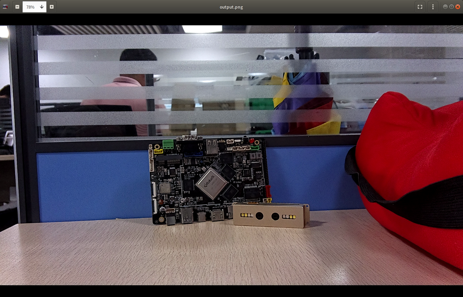
VI->GetFrame
The corresponding DEMO example for this development process is
rkmedia_vi_get_frame_test.cNote: Device input is saved to a file. Show how to fetch a video stream from
VIwithoutBind.Quick use:
# Grab 10 frames from the camera node rkispp_scale0 and save them as a 1080p.nv12 file
./rkmedia_vi_get_frame_test  -a /oem/etc/iqfiles/ -w 1920 -h 1080 -d rkispp_scale0 -o /tmp/1080p.nv12 -c 10

# Select 10 frames of image data, intercept the last frame to preview
# Use dd to skip the first 9 frames to get the last frame. 3110400 = 1920 x 1080 x 3/2 NV12 data size per frame
dd if=1080p.nv12 of=1080pl.nv12 bs=3110400 skip=9
# Convert NV12 images to PNG format using ffmpeg.
fmpeg -y -f rawvideo -pix_fmt nv12 -ss 00:01 -r 1 -s 1920x1080 -i 1080pl.nv12 -frames:v 1 output.png
# Open output.png to preview.
The DEMO effect is shown in the figure below
VI->UVC
The demo example corresponding to the development process is
firefly_rkmediA_vi_uvc_test.cDescription: virtual the device into a network card and UVC
compound device. Device camera inputs and processes image data using anRKNNmodel. Image data is transmitted to host host computer through UVC. RKNN Output data is transmitted to the host host computer through the virtual nic. Host host is developed withOpenCVand can be applied toWindows/Linux/macOSplatforms. This demo is for sdk-ai only. sdk-ai source code link.
# Due to the large number of configuration items, demo has been solidified into MK file, and the demo firmware is generated by one-click compilation using mk file
# Compile command
./build.sh device/rockchip/rv1126_rv1109/aio-rv1126-rkmedia-uvcc.mk
./build.sh

# /etc/init.d/S58_lunch_init The board does not need to do anything. You only need to run the Linux host command.
# Because the demo is not perfect. After executing sudo ./client on the Linux host, restart the device before starting demo again.
Quick use:
# Linux host
sudo ./client
The DEMO effect is shown in the figure below
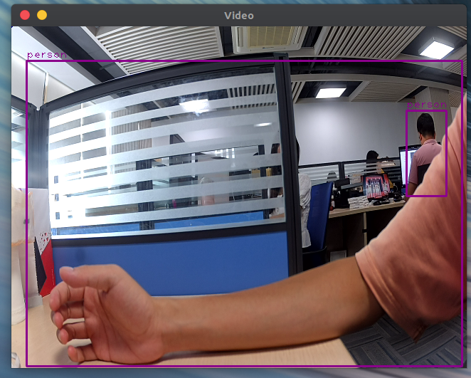
VI->RKNN->VENC->RTSP
The corresponding DEMO example for this development process is
rkmedia_vi_rknn_venc_rtsp_test.cNote: This example parses the rtsp-nn.cfg configuration file to configure the input and output information of the
VIinterface and theVENCinterface. The image data of the camera node obtained by theVIinterface is sent to theNPUforAImodel inference, and then the inference results are analyzed. Then, the processed data is sent to theVENCcoding interface for encoding by using theRK_MPI_SYS_SendMediaBufferinterface. Finally, thertsp_tx_videointerface is used to push theVENCencoded data stream to theRTSPnetwork.Quick use:
# The path needs to have relevant files
./rkmedia_vi_rknn_venc_rtsp_test -a /oem/etc/iqfiles/ -c /oem/usr/share/rtsp-nn.cfg -b /oem/usr/share/rknn_model/box_priors.txt -l /oem/usr/share/rknn_model/coco_labels_list.txt -p /oem/usr/share/rknn_model/ssd_inception_v2_rv1109_rv1126.rknn

# Preview RTSP push stream on PC using VLC player
vlc rtsp://168.168.101.208:554/live/main_stream
# Note: 168.168.101.208 is the IP address of the development board, which can be adjusted according to the actual situation
The DEMO effect is shown in the figure below
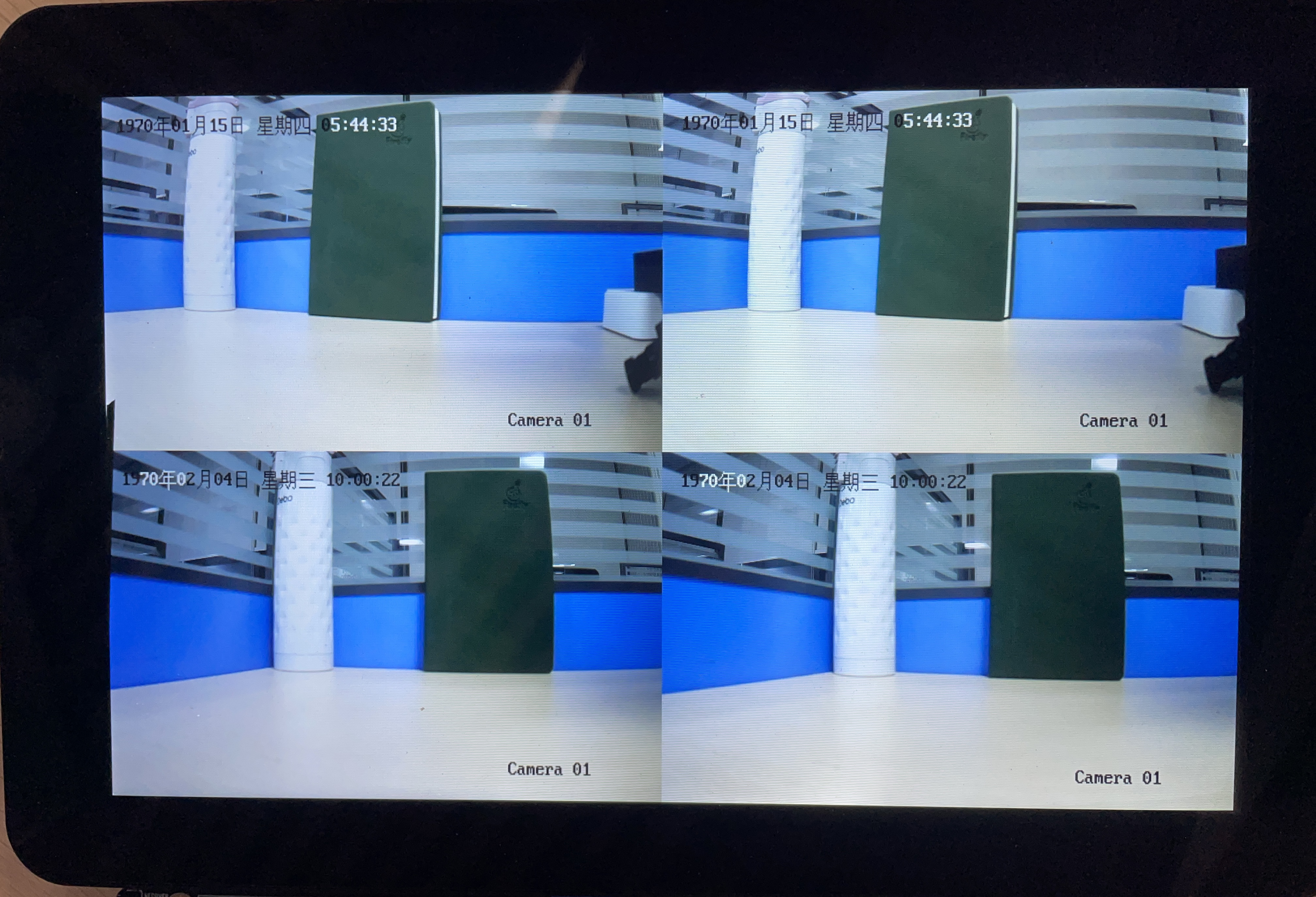
RTSPGet->VDEC(Multi)->VO
The corresponding DEMO example for this development process is
rkmedia_rtspget_multi_test.ccDescription: This example uses the
RTSPpull interfaceffrtspGetto get data from multiple webcams, then uses theVDECinterface to decode, then uses theRGAinterface to accelerate the building of raw data into target data, and finally uses theRK_MPI_SYS_SendMediaBufferinterface to send the target data to theVOinterface for split screen output display.Quick use:
# RTSP fetches 2 webcams, each camera fetches twice, and outputs to display on the display screen
./rkmedia_rtspget_multi_test rtsp://admin:firefly123@168.168.100.94:554/av_stream rtsp://admin:firefly123@168.168.100.94:554/av_stream rtsp://admin:firefly123@168.168.100.97:554/av_stream rtsp://admin:firefly123@168.168.100.97:554/av_stream
The DEMO effect is shown in the figure below
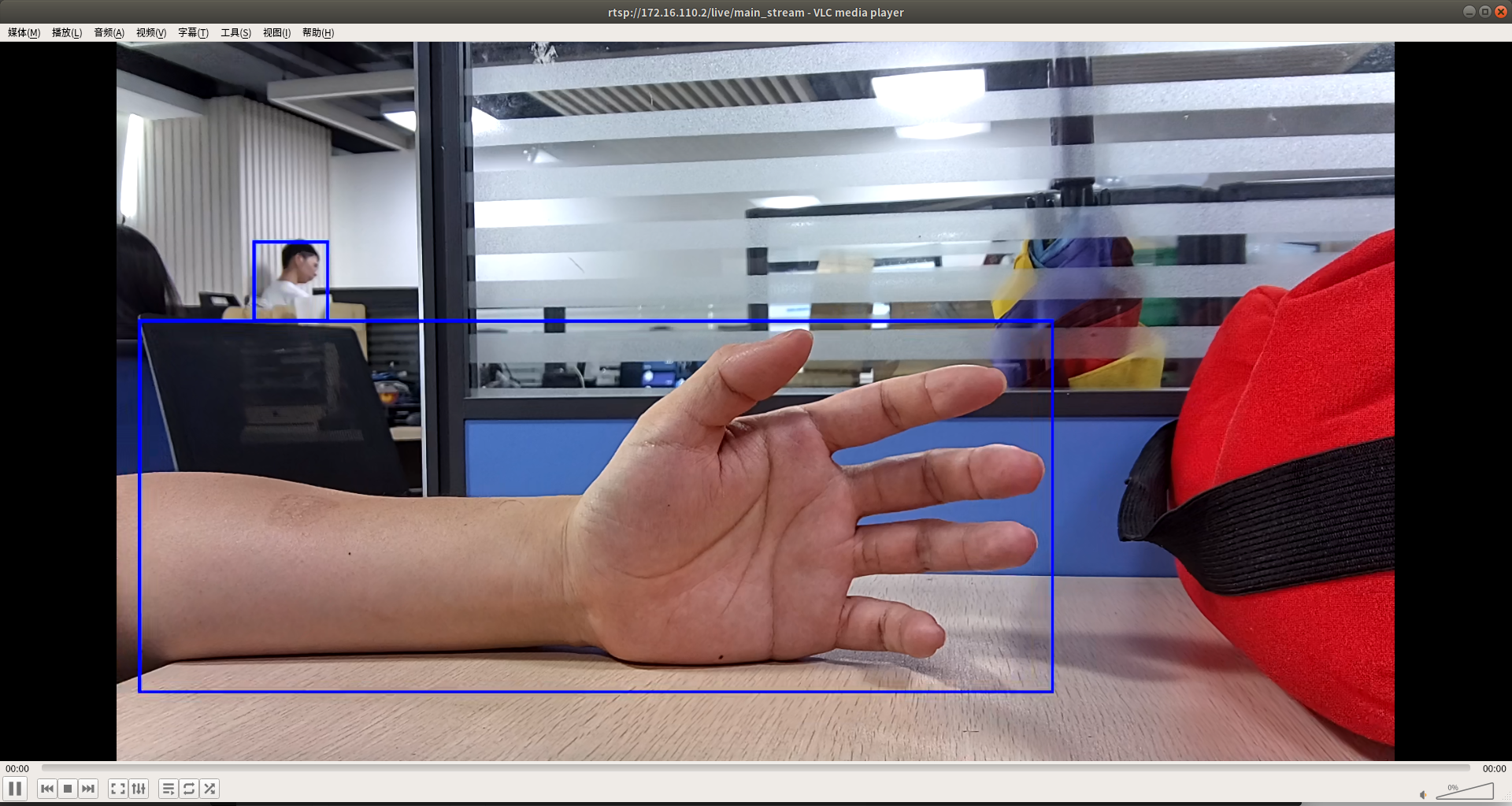
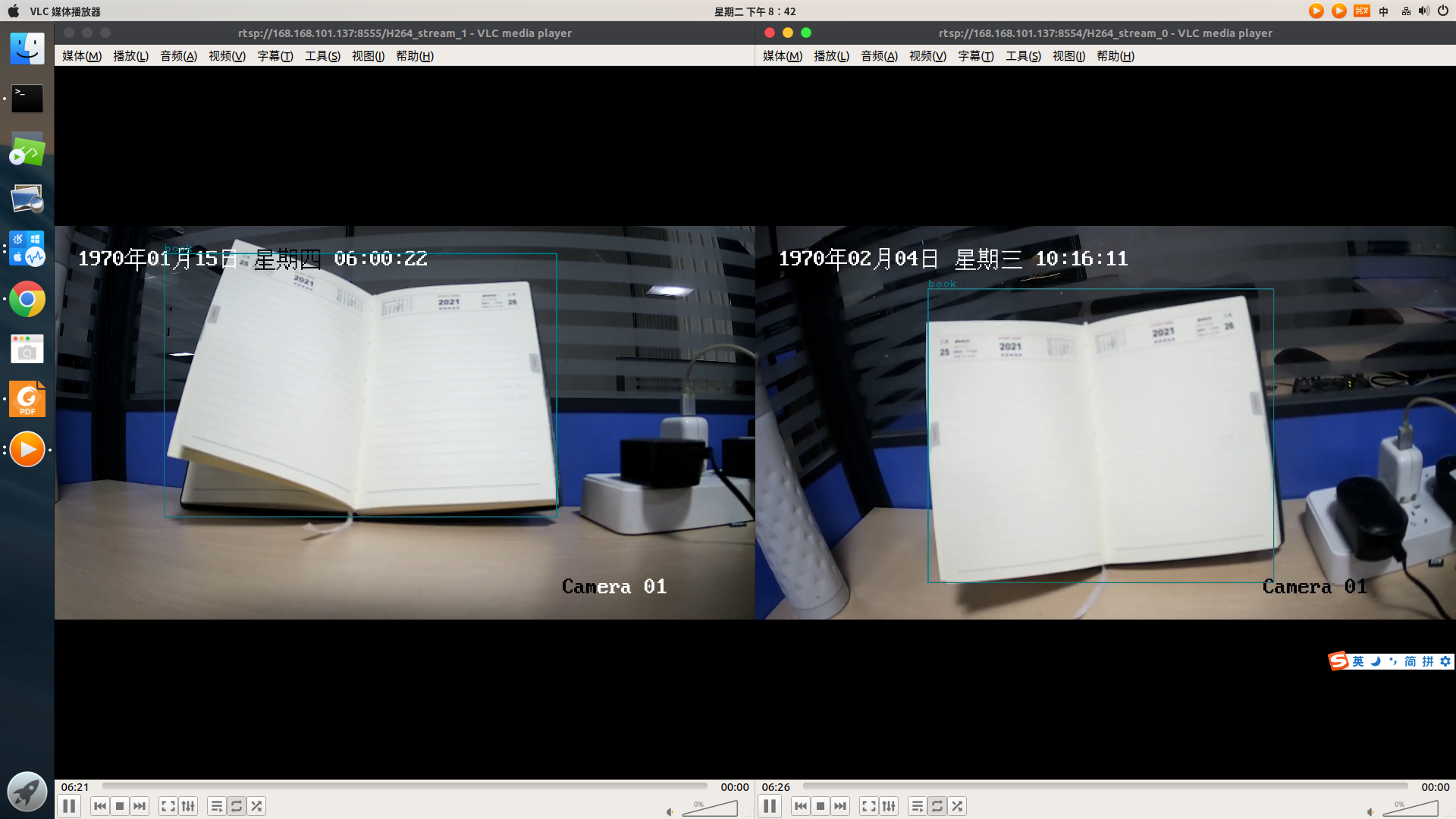
RTSPGet->VDEC->RKNN->VENC->RTSPPush
The corresponding DEMO example for this development process is
rkmedia_rtspget_vdec_rknn_venc_rtsp_test.ccNote: This example can achieve the effect of multiple
RTSPpull stream decoding and multipleRTSPcoding push stream. The process uses theRTSPpull interfaceffrtspGetto get data from multiple webcams, and then uses theVDECinterface to decode. The decoded picture data > is sent toNPUforAImodel reasoning, and then the reasoning results are analyzed. OpenCV is used to apply the reasoning results to the pictures.VENCencodes the images processed by OpenCV, and finally uses the interfaceffrtspPushto push the data stream encoded byVENCStream to theRTSPnetwork.Quick use:
# To run this example, you need the library file libffrtsp.so
./rkmedia_rtspget_vdec_rknn_venc_rtsp_test -c /usr/share/ffrtsp-nn.cfg -p /usr/share/rknn_model/ssd_inception_v2_rv1109_rv1126.rknn -l /usr/share/rknn_model/coco_labels_list.txt -b /usr/share/rknn_model/box_priors.txt

# ffrtsp-nn.cfg The two webcams are configured as
video_type=6 video_fps=25 width=1920 height=1080 image_type=4 port=8554 video_url=rtsp://admin:firefly123@168.168.100.94:554/av_stream
video_type=6 video_fps=25 width=1920 height=1080 image_type=4 port=8555 video_url=rtsp://admin:firefly123@168.168.100.97:554/av_stream

# The command to preview the RTSP push screen using VLC on PC is
vlc rtsp://168.168.101.208:8554/H264_stream_0
vlc rtsp://168.168.101.208:8555/H264_stream_1
# Note: 168.168.101.208 is the IP of the development board, which can be adjusted according to the actual situation
The DEMO effect is shown in the figure below
Audio
Audio function demo example:
rkmedia_audio_test. SupportAI->AENC->AOcycle,AI->AENC->File,File->ADEC->AO,AI input VQE enhanced AO outputfour modes.Quick use:
#Sampling rate. Available options: 0, 16000, 22050, 24000, 32000, 44100, 48000
# AI->AENC->AO
./rkmedia_audio_test 0 16000

# AI->AENC->File
./rkmedia_audio_test 1 16000 /userdata/output.aac

# File->ADEC->AO
./rkmedia_audio_test 2 16000 /userdata/input.aac

# AI input VQE enhanced AO output
./rkmedia_audio_test 3 16000