2. GPIO Use
2.1. Introduction
GPIO(General-Purpose Input/ Output) is a general purpose pin that can be dynamically configured and controlled through running the software.
There are 9 groups of GPIO banks: GPIO0, GPIO1,., GPIO8 on the Firefly-RK3288 development board,and each group is distinguished by A0 ~ A7, B0 ~ B7, C0 ~ C7, D0 ~ D7.
In addition to the general I/O functions, each GPIO port may have additional reuse function such as GPIO5_B4, which can be reused to one of the following functions:
spi0_clk
ts0_data4
uart4exp_ctsn
The drive current, pull-up and pull-down and initial states after resetting of each GPIO port are different. For details, please refer to TRM document.
The GPIO drivers for the Firefly-RK3288 are implemented in the following pinctrl file:
kernel/drivers/pinctrl/pinctrl-rockchip.c
Its core is the way and the parameters for populating the GPIO bank, and to call the gpiochip_add to register into the kernel.
2.2. Use
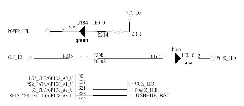
There are two power LEDs controlled by the GPIO port for the development board:

From the schematic, the led will be on if outputing low voltage level from GPIO, and off if high voltage level otherwse.
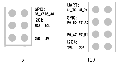
Additionally, the extension slots have exported serveral GPIOs not used by system, which are:

There GPIOs can be customized for input or output use.
2.3. I/O
Let’s take the driver of the power LED as an example to describe how to write the code in the kernel to control the output of the GPIO port.
First, you need to add a resource description of driver in the firefly-rk3288-aio-3288j.dts:
firefly-led{
    compatible = "firefly,led";
    led-work = <&gpio8 GPIO_A2 GPIO_ACTIVE_LOW>;
    led-power = <&gpio8 GPIO_A1 GPIO_ACTIVE_LOW>;
    status = "okay";
};
The GPIO settings for two LEDs are defined here:
led-work  GPIO8_A2  GPIO_ACTIVE_LOW
led-power GPIO8_A1  GPIO_ACTIVE_LOW
GPIO_ACTIVE_LOW indicates active-low, and it needs to be replaced by GPIO_ACTIVE_HIGH if it is active-high.
Then the application and control of the GPIO port can be added to the driver:
#ifdef  CONFIG_OF
#include <linux/of.h>
#include <linux/of_gpio.h>
#endif
static int firefly_led_probe(struct platform_device *pdev){
    int ret = -1;int gpio, flag;
    struct device_node *led_node = pdev->dev.of_node;
    gpio = of_get_named_gpio_flags(led_node, "led-power", 0, &flag);
    if (!gpio_is_valid(gpio)){
        printk("invalid led-power: %d\n",gpio);
        return -1;
    }
    if (gpio_request(gpio, "led_power")) {
        printk("gpio %d request failed!\n",gpio);
        return ret;
    }
    led_info.power_gpio = gpio;
    led_info.power_enable_value = (flag == OF_GPIO_ACTIVE_LOW) ? 0 : 1;
    gpio_direction_output(led_info.power_gpio, !(led_info.power_enable_value));
    ...
    on_error:gpio_free(gpio);
}
The of_get_named_gpio_flags read the GPIO configuration number and flags for led-power from the device tree, then the gpio_is_valid determines whether the GPIO number is valid, and the gpio_request requests to occupy the GPIO. If an error occurs during initialization, the gpio_free is required to be called to release the GPIO that was previously applied successfully.
The high-level output or low-level output can be set by calling the gpio_direction_output since it is GPIO_ACTIVE_LOW, and if you write 0 into it, the light will be on.
In practice, if the GPIO is to be read, it needs to be set to input mode before reading the value:
int val;
gpio_direction_input(your_gpio);
val = gpio_get_value(your_gpio);
The following are the commonly used GPIO API definitions:
#include <linux/gpio.h>
#include <linux/of_gpio.h>
enum of_gpio_flags {
    OF_GPIO_ACTIVE_LOW = 0x1,
};
int of_get_named_gpio_flags(struct device_node *np, const char *propname,
                int index, enum of_gpio_flags *flags);
int gpio_is_valid(int gpio);
int gpio_request(unsigned gpio, const char *label);
void gpio_free(unsigned gpio);
int gpio_direction_input(int gpio);
int gpio_direction_output(int gpio, int v);
2.4. Reuse
How to define which functions of GPIO can be reused, and how to switch the functions while running? I2C4 is taken as an example to give a brief introduction.
You can learn from the specification table, the functions of I2C4_SDA and I2C4_SCL are defined as follows:

In /kernel/arch/arm/boot/dts/rk3288.dtsi, there are:
i2c4: i2c@ff160000 {
    compatible = "rockchip,rk30-i2c";
    reg = <0xff160000 0x1000>;
    interrupts = <GIC_SPI 64 IRQ_TYPE_LEVEL_HIGH>;
    #address-cells = <1>;
    #size-cells = <0>;
    pinctrl-names = "default", "gpio";
    pinctrl-0 = <&i2c4_sda &i2c4_scl>;
    pinctrl-1 = <&i2c4_gpio>;
    gpios = <&gpio7 GPIO_C1 GPIO_ACTIVE_LOW>, <&gpio7 GPIO_C2 GPIO_ACTIVE_LOW>;
    clocks = <&clk_gates6 15>;
    rockchip,check-idle = <1>;
    status = "disabled";
};
Here, the attribute that starts with pinctrl- is related to the multiplex control:
The pinctrl-names defines the list of state names: default (i2c function) and gpio
The pinctrl-0 defines the pinctrl to be set at the state of 0(i.e. default): i2c4_sda and i2c4_scl
The pinctrl-1 defines the pinctrl to be set at the state of 1(i.e. gpio): i2c4_gpio
These pinctl are defined in /kernel/arch/arm/boot/dts/rk3288-pinctrl.dtsi:
/ {
    pinctrl: pinctrl@ff770000 {
    compatible = "rockchip,rk3288-pinctrl";
    ...
    gpio7_i2c4 {
        i2c4_sda:i2c4-sda {
            rockchip,pins = <I2C4TP_SDA>;
            rockchip,pull = <VALUE_PULL_DISABLE>;
            rockchip,drive = <VALUE_DRV_DEFAULT>;
            //rockchip,tristate = <VALUE_TRI_DEFAULT>;
        };
        i2c4_scl:i2c4-scl {
            rockchip,pins = <I2C4TP_SCL>;
            rockchip,pull = <VALUE_PULL_DISABLE>;
            rockchip,drive = <VALUE_DRV_DEFAULT>;
            //rockchip,tristate = <VALUE_TRI_DEFAULT>;
        };
        i2c4_gpio: i2c4-gpio {
            rockchip,pins = <FUNC_TO_GPIO(I2C4TP_SDA)>, <FUNC_TO_GPIO(I2C4TP_SCL)>;
            rockchip,drive = <VALUE_DRV_DEFAULT>;
        };
    };
    ...
}
I2C4TP_SDA, I2C4TP_SCL is defined in /kernel/arch/arm/boot/dts/include/dt-bindings/pinctrl/rockchip-rk3288.h:
#define GPIO7_C1 0x7c10
#define I2C4TP_SDA 0x7c11
#define GPIO7_C2 0x7c20
#define I2C4TP_SCL 0x7c21
FUN_TO_GPIO is defined in /kernel/arch/arm/boot/dts/include/dt-bindings/pinctrl/rockchip.h:
#define FUNC_TO_GPIO(m) ((m) & 0xfff0)
That is, FUNC_TO_GPIO(I2C4TP_SDA) == GPIO7_C1, FUNC_TO_GPIO(I2C4TP_SCL) == GPIO7_C2.
There are the coding rules for the values like 0x7c11:
7 c1 1
| |  `- func
| `---- offset
`------ bank
0x7c11 stands for GPIO7_C1 func1, that is, I2C4TP_SDA.
When multiplexing, if you select “default” (i.e. i2c function), two pinctrls(i2c1_sda and i2c1_scl) are applied by the system, and both GPIO0_A3 and GPIO0_A2 pins are switched to the corresponding i2c function, and if the “gpio” is selected, the pinctrl(i2c1_gpio) will be applied by the system, and the two pins GPIO0_A3 and GPIO0_A2 are restored to the GPIO function.
Let’s take a look at how the i2c driver /kernel/drivers/i2c/busses/i2c-rockchip.c switches the reuse function:
static int rockchip_i2c_probe(struct platform_device *pdev){
    struct rockchip_i2c *i2c = NULL;
    struct resource *res;
    struct device_node *np = pdev->dev.of_node;
    int ret;
    // ...
    i2c->sda_gpio = of_get_gpio(np, 0);
    if (!gpio_is_valid(i2c->sda_gpio)) {
        dev_err(&pdev->dev, "sda gpio is invalid\n");
        return -EINVAL;
    }
    ret = devm_gpio_request(&pdev->dev, i2c->sda_gpio, dev_name(&i2c->adap.dev));
    if (ret) {
        dev_err(&pdev->dev, "failed to request sda gpio\n");
        return ret;
    }
    i2c->scl_gpio = of_get_gpio(np, 1);
    if (!gpio_is_valid(i2c->scl_gpio)) {
        dev_err(&pdev->dev, "scl gpio is invalid\n");
        return -EINVAL;
    }
    ret = devm_gpio_request(&pdev->dev, i2c->scl_gpio, dev_name(&i2c->adap.dev));
    if (ret) {
        dev_err(&pdev->dev, "failed to request scl gpio\n");
        return ret;
    }
    i2c->gpio_state = pinctrl_lookup_state(i2c->dev->pins->p, "gpio");
    if (IS_ERR(i2c->gpio_state)) {
        dev_err(&pdev->dev, "no gpio pinctrl state\n");
        return PTR_ERR(i2c->gpio_state);
    }
    pinctrl_select_state(i2c->dev->pins->p, i2c->gpio_state);
    gpio_direction_input(i2c->sda_gpio);
    gpio_direction_input(i2c->scl_gpio);
    pinctrl_select_state(i2c->dev->pins->p, i2c->dev->pins->default_state);
    // ...
}
First, the of_get_gpio is called to extract the gpios of the i2c4 node in the device tree belonging to the two defined gpio:
gpios = <&gpio7 GPIO_C1 GPIO_ACTIVE_LOW>, <&gpio7 GPIO_C2 GPIO_ACTIVE_LOW>;
Then the devm_gpio_request is called to request gpio, and then the pinctrl_lookup_state is called to find the “gpio” status, but the default status “default” has been saved from the frame to i2c->dev-pins->default_state.
Finally, pinctrl_select_state is called to select “default” or “gpio” function. The following are the commonly used reuse APIs definitions:
#include <linux/pinctrl/consumer.h>
struct device {
    //...
    #ifdef CONFIG_PINCTRL
    struct dev_pin_info *pins;
    #endif
    //...
};
struct dev_pin_info {
    struct pinctrl *p;
    struct pinctrl_state *default_state;
    #ifdef CONFIG_PMstruct pinctrl_state *sleep_state;
    struct pinctrl_state *idle_state;
    #endif
};
struct pinctrl_state * pinctrl_lookup_state(struct pinctrl *p, const char *name);
int pinctrl_select_state(struct pinctrl *p, struct pinctrl_state *s);
