MIPI CSI
Introduction
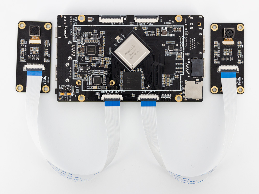
ROC-3399-PC-PLUS Development board with two MIPI, The default is OV13850 cameras
This article takes OV13850 camera as an example to explain the configuration process on the development board.
Interface rendering
DTS configuration
isp0: isp@ff910000 {
    ...
    status = "okay";
}
isp1: isp@ff920000 {
    ...
    status = "okay";
}
Driving instructions
The directory of camera codes is as follows:
Android:
 `- hardware/rockchip/camera/
    |- CameraHal             // Camera HAL source code
    `- SiliconImage          // ISP library, including all support module driver source code
       `- isi/drv/OV13850    // OV13850 module driver source code
          `- calib/OV13850.xml // OV13850 module calibration parameters
 `- device/rockchip/rk3399/
    |- rk3399_roc_pc
    |  `- cam_board.xml      // Camera parameter Settings

 Kernel:
 |- kernel/drivers/media/video/rk_camsys  // CamSys drive source code
 `- kernel/include/media/camsys_head.h
Configuration principle
The configuration process can be completed by setting camera-related pins and clocks.
The schematic diagram of camera interface is as follows. Pins to be configured are DVP_PWR, CIF_PWR, MIPI_RST and DVP_PDN0.
mipi interface
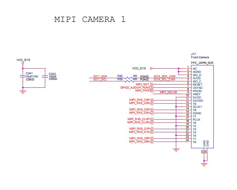
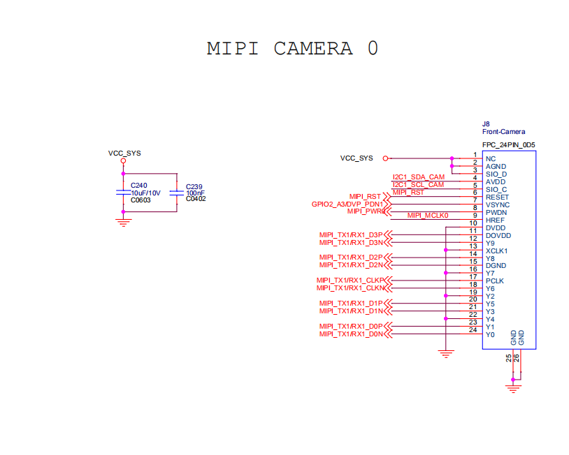
In the development board, except for CIF_POWER to be set in DTS, the other pins are set in cam_board.xml.
Configuration steps
Configure Android
Modify device/rockchip/rk3399/rk3399_roc_pc/cam_board.xml to register the camera :
...
                <Sensor>
                    <SensorName name="OV13850" ></SensorName>
                    <SensorLens name="50013A1"></SensorLens>
                    <SensorDevID IDname="CAMSYS_DEVID_SENSOR_1A"></SensorDevID>
                    <SensorHostDevID busnum="CAMSYS_DEVID_MARVIN" ></SensorHostDevID>
                    <SensorI2cBusNum busnum="1"></SensorI2cBusNum>
                    <SensorI2cAddrByte byte="2"></SensorI2cAddrByte>
                    <SensorI2cRate rate="100000"></SensorI2cRate>
                    <SensorAvdd name="NC" min="28000000" max="28000000" delay="0"></SensorAvdd>
                    <SensorDvdd name="NC" min="12000000" max="12000000" delay="0"></SensorDvdd>
                    <SensorDovdd name="NC" min="18000000" max="18000000" delay="5000"></SensorDovdd>
                    <SensorMclk mclk="24000000" delay="1000"></SensorMclk>
                    <SensorGpioPwen ioname="RK30_PIN1_PC7" active="1" delay="1000"></SensorGpioPwen>
                    <SensorGpioRst ioname="RK30_PIN0_PB0" active="0" delay="1000"></SensorGpioRst>
                    <SensorGpioPwdn ioname="RK30_PIN2_PA2" active="0" delay="0"></SensorGpioPwdn>
                    <SensorFacing facing="back"></SensorFacing>
                    <SensorInterface interface="MIPI"></SensorInterface>
                    <SensorMirrorFlip mirror="0"></SensorMirrorFlip>
                    <SensorOrientation orientation="180"></SensorOrientation>
                    <SensorPowerupSequence seq="1234"></SensorPowerupSequence>
                    <SensorFovParemeter h="60.0" v="60.0"></SensorFovParemeter>
                    <SensorAWB_Frame_Skip fps="15"></SensorAWB_Frame_Skip>
                    <SensorPhy phyMode="CamSys_Phy_Mipi" lane="2"  phyIndex="0" sensorFmt="CamSys_Fmt_Raw_10b"></SensorPhy>
                </Sensor>
...

                <Sensor>
                    <SensorName name="OV13850" ></SensorName>
                    <SensorLens name="50013A1"></SensorLens>
                    <SensorDevID IDname="CAMSYS_DEVID_SENSOR_1B"></SensorDevID>
                    <SensorHostDevID busnum="CAMSYS_DEVID_MARVIN" ></SensorHostDevID>
                    <SensorI2cBusNum busnum="1"></SensorI2cBusNum>
                    <SensorI2cAddrByte byte="2"></SensorI2cAddrByte>
                    <SensorI2cRate rate="100000"></SensorI2cRate>
                    <SensorAvdd name="NC" min="28000000" max="28000000" delay="0"></SensorAvdd>
                    <SensorDvdd name="NC" min="12000000" max="12000000" delay="0"></SensorDvdd>
                    <SensorDovdd name="NC" min="18000000" max="18000000" delay="5000"></SensorDovdd>
                    <SensorMclk mclk="24000000" delay="1000"></SensorMclk>
                    <SensorGpioPwen ioname="RK30_PIN1_PC7" active="1" delay="1000"></SensorGpioPwen>
                    <SensorGpioRst ioname="RK30_PIN0_PB0" active="0" delay="1000"></SensorGpioRst>
                    <SensorGpioPwdn ioname="RK30_PIN2_PA3" active="0" delay="0"></SensorGpioPwdn>
                    <SensorFacing facing="front"></SensorFacing>
                    <SensorInterface interface="MIPI"></SensorInterface>
                    <SensorMirrorFlip mirror="0"></SensorMirrorFlip>
                    <SensorOrientation orientation="180"></SensorOrientation>
                    <SensorPowerupSequence seq="1234"></SensorPowerupSequence>
                    <SensorFovParemeter h="60.0" v="60.0"></SensorFovParemeter>
                    <SensorAWB_Frame_Skip fps="15"></SensorAWB_Frame_Skip>
                    <SensorPhy phyMode="CamSys_Phy_Mipi" lane="2"  phyIndex="1" sensorFmt="CamSys_Fmt_Raw_10b"></SensorPhy>
                </Sensor>

...
The main changes are as follows :
Sensor name
<SensorName name="OV13850" ></SensorName>
The name must be the same as the name of the Sensor driver. The format of the Sensor driver currently provided is as follows:
libisp_isi_drv_OV13850.so
Sensor software identification
<SensorDevID IDname="CAMSYS_DEVID_SENSOR_1A"></SensorDevID>
If the registration mark is inconsistent, you can fill in the following values:
CAMSYS_DEVID_SENSOR_1A
CAMSYS_DEVID_SENSOR_1B
CAMSYS_DEVID_SENSOR_2
Acquisition controller name
<SensorHostDevID busnum="CAMSYS_DEVID_MARVIN" ></SensorHostDevID>
Currently only supported:
CAMSYS_DEVID_MARVIN
Sensor is connected to the main control I2C channel number
<SensorI2cBusNum busnum="1"></SensorI2cBusNum>
For the specific channel number, please refer to the schematic diagram of the camera to connect to the I2C channel number of the main control.
Sensor register address length, unit: bytes
<SensorI2cAddrByte byte="2"></SensorI2cAddrByte>
Sensor I2C frequency, unit: Hz, for setting the frequency of I2C.
<SensorI2cRate rate="100000"></SensorI2cRate>
Sensor input clock frequency, unit: Hz, used to set the camera clock.
<SensorMclk mclk="24000000"></SensorMclk>
Sensor, The PMU LDO name of AVDD. If you are not connected to PMU, just fill in the NC.
<SensorAvdd name="NC" min="28000000" max="28000000" delay="0"></SensorAvdd>
Sensor, The PMU LDO name of DOVDD.
<SensorDovdd name="NC" min="18000000" max="18000000" delay="5000"></SensorDovdd>
If you are not connected to PMU, just fill in the NC. Note that min and max values must be filled in, which determines the IO voltage of the Sensor.
Sensor, The PMU LDO name of DVDD.
<SensorDvdd name="NC" min="12000000" max="12000000" delay="0"></SensorDvdd>
If you are not connected to PMU, just fill in the NC.
Sensor PowerDown pin
<SensorGpioPwdn ioname="RK30_PIN2_PA2" active="0" delay="0"></SensorGpioPwdn>
Directly fill in the name, active fill in the effective level of sleep.
Sensor Reset pin
<SensorGpioRst ioname="RK30_PIN0_PB0" active="0" delay="1000"></SensorGpioRst>
Directly fill in the name, fill in the effective reset level of direct active.
Sensor Power pin
<SensorGpioPwen ioname="RK30_PIN1_PC7" active="1" delay="1000"></SensorGpioPwen>
Directly fill in the name, fill in the effective level of the power supply for active.
Select Sensor as front or rear
<SensorFacing facing="back"></SensorFacing>
Fill in “front” or “back”.
Sensor interface mode
<SensorInterface mode="MIPI"></SensorInterface>
You can fill in the following values:
CCIR601
CCIR656
MIPI
SMIA
Sensor mirroring mode
<SensorMirrorFlip mirror="0"></SensorMirrorFlip>
Currently not supported.
Sensor Angle information
<SensorOrientation orientation="0"></SensorOrientation>
Physical interface setup
MIPI
<SensorPhy phyMode="CamSys_Phy_Mipi" lane="2" phyIndex="0" sensorFmt="CamSys_Fmt_Raw_10b"></SensorPhy>
hyMode:Sensor interface hardware connection mode, For the MIPI Sensor, take “CamSys_Phy_Mipi”.
Lane:Sensor Mipi interface data channel number.
Phyindex:Sensor Mipi’s main control mipi phy number.
sensorFmt:Sensor output data format, currently only support CamSys_Fmt_Raw_10b
To compile the kernel, the drivers/media/video/rk_camsys driver source code should be compiled into the kernel. The configuration method is as follows:
Execute the command in the kernel source directory:
make menuconfig
Then open the following configuration items:
Device Drivers  --->
 Multimedia support  --->
        camsys driver
         RockChip camera system driver  --->
                   camsys driver for marvin isp
                   camsys driver for cif
Final execution:
make ARCH=arm64 rk3399-firefly-aio.img
The kernel can be compiled.
Debug method
Under the terminal, you can directly modify /system/etc/cam_board.xml to debug various parameters and restart to take effect.
FAQs
1. Unable to open the camera, first ensure whether the sensor I2C communicates. If not, then can check MCLK and Power supply is normal (Power/PowerDown/Reset/MCLK/I2cBus), respectively.
2. Support list
13Mː OV13850/IMX214-0AQH5
8Mː OV8825/OV8820/OV8858-Z(R1A)/OV8858-R2A
5Mː OV5648/OV5640
2Mː OV2680
Consult the SDK/RKDocs for details.