Wiegand
Intruduction
Wiegand protocol is a communication protocol developed by Motorola, which is applicable to many aspects of card readers and cards related to access control system; the protocol does not define the baud rate of communication and data length. It mainly defines the data transmission mode: Data0 and data1 are used to transmit 0 and 1 respectively. They are mostly used for 26bit, 34bit, 36bit, 44bit, etc.

Debugging
The RS485 port of Face-RK3399 can be reused as the sending port of Wiegand protocol for data transmission.
DTS configuration
The Wiegand node is defined in kernel/arch/arm64/boot/dts/rockchip/rk3399-firefly-face.dtsi:
wiegand-gpio {
    compatible = "firefly,wiegandout";
    level_effect = <1>;/*0-low effect 1-high effect*/
    gpio_d0 = <&gpio1 9 GPIO_ACTIVE_HIGH>;
    gpio_d1 = <&gpio1 10 GPIO_ACTIVE_HIGH>;
    gpio_mode_switch = <&gpio1 17 GPIO_ACTIVE_HIGH>;
    status = "okay";
Run commands in device as follow:
echo 0 > /sys/devices/platform/wiegand-gpio/mode_switch  #Switch to Wiegand interface function
echo [card number] > /sys/devices/platform/wiegand-gpio/wiegand26 # Sending Wiegand 26 date
echo [card number] > /sys/devices/platform/wiegand-gpio/wiegand34 # sending Wiegand 34 function
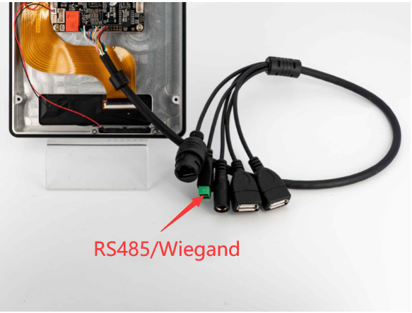
The following is the specific wiring method of Wigan transmission interface. Note that VCC and GND need to be provided through USB.

Wiegand interface can also as GPIO:
# Pull up D0
echo 1 > /sys/devices/platform/wiegand-gpio/D0
# Pull up D1
echo 1 > /sys/devices/platform/wiegand-gpio/D1
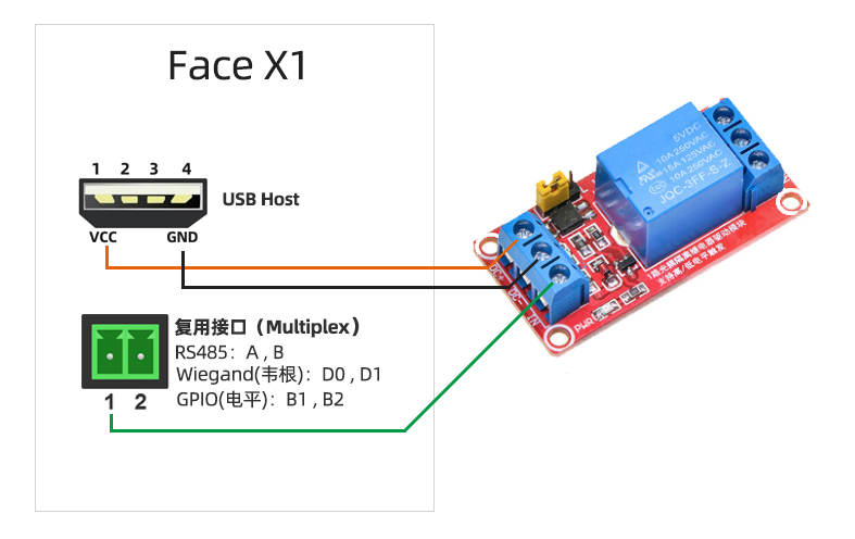
The following is the connection diagram of control relay with D0, D1, IO port. Note that VCC and GND need to be provided through USB.
V2 Wiegand and relay
In Face-RK3399 V2, the Wiegand interface is updated while it using expansion board. You can lookup by interface definition
NOTE:GND connectting is needed
V2 Wiegand output
Run commands in device as follow:
echo card number > /sys/devices/platform/wiegand-gpio/wiegand26 # Sending Wiegand 26 date
echo card number > /sys/devices/platform/wiegand-gpio/wiegand34 # sending Wiegand 34 function
V2 Wiegand input
File system create the node /dev/wiegand.
The following example of Wigand input program:
#include <stdio.h>
#include <sys/types.h>
#include <sys/stat.h>
#include <fcntl.h>
#include <unistd.h>
#include <errno.h>
#include <asm-generic/ioctl.h>

#define WG_IOC_MAGIC 'k'

#define WG_IOCGETFUN    _IOR(WG_IOC_MAGIC, 1, int)
#define WG_IOC_FUN_IN   _IOR(WG_IOC_MAGIC, 2, int)  //Set to normal input IO
#define WG_IOC_FUN_WG   _IOR(WG_IOC_MAGIC, 3, int)  //Set ti Wiegand input IO
#define WG_IOCGETD0     _IOR(WG_IOC_MAGIC, 4, int)  //Get IO level
#define WG_IOCGETD1     _IOR(WG_IOC_MAGIC, 5, int)
#define WG_IOCGETWG     _IOR(WG_IOC_MAGIC, 6, int)  //Get Wiegand data

int main()
{
    int fd = 0;
    char dst[12] = { 0};
    int val;
    int result =0;
    fd = open("/dev/wiegand", O_RDWR);
    if(fd < 0)
    {
        printf("file open error ! \n");
        return -1;
    }
    while(1)
    {
        //result=read(fd, dst, sizeof(dst));
        ioctl(fd, WG_IOC_FUN_WG, &val);
        result = ioctl(fd, WG_IOCGETWG, &val);
        if(result < 0) {
            printf("Unable to get value: %s\n", strerror(errno));
            close(fd);
            return -1;
        } else
            printf("val is %d, size=%d\n", val,result);
        sleep(1);
    }
    /*close the device*/
    close(fd);

    return 0;
}
The above program can receive and print the input data of Wiegand.
V2 relay
The relay of V2 can control two lines ON/OFF refer to interface definition
echo 0 > /sys/devices/platform/wiegand-gpio/mode_switch # COM and ON connect
echo 1 > /sys/devices/platform/wiegand-gpio/mode_switch # COM and OFF connect