1. ADC 使用
1.1. 简介
AIO-3588Q 开发板上的 AD 接口有两种,分别为:温度传感器 (Temperature Sensor)、逐次逼近ADC (Successive Approximation Register)。其中:
TS-ADC(Temperature Sensor):支持七通道。
SAR-ADC(Successive Approximation Register):支持八通道单端12位的SAR-ADC,最大转换速率为1MSPS,采用20MHz的A/D转换器时钟。
内核采用工业 I/O 子系统来控制 ADC,该子系统主要为 AD 转换或者 DA 转换的传感器设计。 下面以 SAR-ADC 为例子,介绍 ADC 的基本配置方法。
1.3. DTS配置
1.3.1. 配置DTS节点
AIO-3588Q SAR-ADC 的 DTS 节点在 kernel-5.10/arch/arm64/boot/dts/rockchip/rk3588s.dtsi 文件中定义,如下所示:
saradc: saradc@fec10000 {
     compatible = "rockchip,rk3588-saradc";
     reg = <0x0 0xfec10000 0x0 0x10000>;
     interrupts = <GIC_SPI 398 IRQ_TYPE_LEVEL_HIGH>;
     #io-channel-cells = <1>;
     clocks = <&cru CLK_SARADC>, <&cru PCLK_SARADC>;
     clock-names = "saradc", "apb_pclk";
     resets = <&cru SRST_P_SARADC>;
     reset-names = "saradc-apb";
     status = "disabled";
};
用户首先需在 DTS 文件中添加 ADC 的资源描述:
kernel-5.10/arch/arm64/boot/dts/rockchip/rk3588-firefly-demo.dtsi :

adc_demo: adc_demo{
     compatible = "firefly,rk3588-adc";
     status = "disabled";
     io-channels = <&saradc 6>;
};
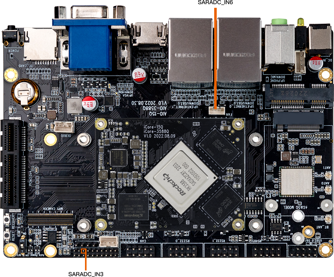
开发板上有两个对外的adc引脚为SARADC通道6和SARADC通道3, 这里申请的是SARADC通道6,它是连接风扇的一个adc。
1.3.2. 在驱动文件中匹配 DTS 节点
用户驱动可参考 Firefly adc demo :kernel-5.10/drivers/iio/adc/adc-firefly-demo.c,这是一个侦测 AIO-3588Q 风扇状态的驱动。首先在驱动文件中定义 of_device_id 结构体数组:
static const struct of_device_id firefly_adc_match[] = {
    { .compatible = "firefly,rk3588-adc" },
    {},
};
然后将该结构体数组填充到要使用 ADC 的 platform_driver 中:
static struct platform_driver firefly_adc_driver = {
    .probe      = firefly_adc_probe,
    .remove     = firefly_adc_remove,
    .driver     = {
        .name   = "firefly_adc",
        .owner  = THIS_MODULE,
        .of_match_table = firefly_adc_match,
    },
};
接着在 firefly_adc_probe 中对 DTS 所添加的资源进行解析:
static int firefly_adc_probe(struct platform_device *pdev)
{
     printk("firefly_adc_probe!\n");
     count = 0;
     chan = iio_channel_get(&(pdev->dev), NULL);
     if (IS_ERR(chan))
     {
          chan = NULL;
          printk("%s() have not set adc chan\n", __FUNCTION__);
          return -1;
     }
     fan_insert = false;
     if (chan) {
          INIT_DELAYED_WORK(&adc_poll_work, firefly_demo_adc_poll);
          schedule_delayed_work(&adc_poll_work,1000);
     }
     return 0;
}
1.4. 驱动说明
1.4.1. 获取 AD 通道
struct iio_channel *chan;     #定义 IIO 通道结构体
chan = iio_channel_get(&pdev->dev, NULL);    #获取 IIO 通道结构体
注意: iio_channel_get 通过 probe 函数传进来的参数 pdev 获取 IIO 通道结构体,probe 函数如下:
static int XXX_probe(struct platform_device *pdev);
1.4.2. 读取 AD 采集到的原始数据
int val,ret;
ret = iio_read_channel_raw(chan, &val);
调用 iio_read_channel_raw 函数读取 AD 采集的原始数据并存入 val 中。
1.4.3. 计算采集到的电压
使用标准电压将 AD 转换的值转换为用户所需要的电压值。其计算公式如下:
Vref / (2^n-1) = Vresult / raw
注意:
Vref 为标准电压
n 为 AD 转换的位数
Vresult 为用户所需要的采集电压
raw 为 AD 采集的原始数据
例如,标准电压为 1.8V,AD 采集位数为 12 位,AD 采集到的原始数据为 445,则:
Vresult = (1800mv * 445) / 4095;
1.5. 接口说明
struct iio_channel *iio_channel_get(struct device *dev, const char *consumer_channel);
功能:获取 iio 通道描述
参数:
dev: 使用该通道的设备描述指针
consumer_channel: 该设备所使用的 IIO 通道描述指针
void iio_channel_release(struct iio_channel *chan);
功能:释放 iio_channel_get 函数获取到的通道
参数:
chan:要被释放的通道描述指针
int iio_read_channel_raw(struct iio_channel *chan, int *val);
功能:读取 chan 通道 AD 采集的原始数据。
参数:
chan:要读取的采集通道指针
val:存放读取结果的指针
1.6. 调试方法
1.6.1. Demo 程序使用
在 kernel-5.10/arch/arm64/boot/dts/rockchip/rk3588-firefly-demo.dtsi 中使能 adc_demo ,将 disabled 改为 okay:
adc_demo: adc_demo{
     status = "okay";
     compatible = "firefly,rk3588-adc";
     io-channels = <&saradc 6>;
};
编译内核,烧录内核到 AIO-3588Q 开发板上,然后插拔风扇时,会打印内核 log 信息如下:
[   73.513351][  T173] Fan insert! raw= 449 Voltage= 197mV
[   75.893182][  T173] Fan out! raw= 4095 Voltage=1800mV

