5. LCD
5.1. 简介
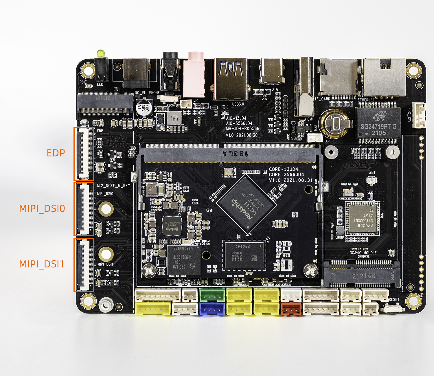
AIO-3566JD4 development board supports two MIPI screen interfaces and one EDP screen interface, which is dsi0.The position of the interface on the board is as follows:
5.2. Config Configuration
In AIO-3566JD4 SDK, the default configuration file kernel/arch/arm64/configs/firefly_defconfig of Core-3566JD4 has already set the LCD-related configuration. If you modify it yourself, please pay attention to it. The following configuration is added:
CONFIG_DRM_ROCKCHIP=y
CONFIG_ROCKCHIP_DW_MIPI_DSI=y
CONFIG_DRM_PANEL_SIMPLE=y
5.3. MIPI DTS Configuration
AIO-3566JD4 SDK has MIPI DSI DTS file:kernel/arch/arm64/boot/dts/rockchip/rk3566-firefly-aiojd4-mipi101_JDM101014_BC45_A1.dts,we would take the dsi0 configuration as an example to introduce the related LCD driver.
5.3.1. Pin Configuration
we can see the following statement from the DTS file:
&dsi0 {
	status = "okay";
	rockchip,lane-rate = <500>;
	dsi0_panel: panel@0 {
	...
        enable-gpios = <&gpio4 RK_PB5 GPIO_ACTIVE_HIGH>;
        reset-gpios = <&gpio3 RK_PC6 GPIO_ACTIVE_LOW>;
	...
};
The power control pins of the LCD are defined here:
| NAME | GPIO | GPIO_ACTIVE |
|---|---|---|
| reset-gpios | GPIO3_C6 | GPIO_ACTIVE_LOW |
| enable-gpios | GPIO4_B5 | GPIO_ACTIVE_HIGH |
On the hardware signal, the enable-gpios is active at high level and reset_gpios is active at low levle. Please refer to the section “GPIO Usage” for specific pin configuration.
5.3.2. Backlight Configuration
The backlight information is configured in the DTS file, as follows:
backlight:backlight {
		status = "okay";
		compatible = "pwm-backlight";
		pwms = <&pwm4 0 50000 1>;
		brightness-levels = <
		     60  60  60  61  61  61  62  62
		     62  63  63  63  64  64  64  65
		     65  65  66  66  66  67  67  67
		     68  68  68  69  69  69  70  70
		     70  71  71  71  72  72  72  73
		     73  73  74  74  74  75  75  75
		     76  76  76  77  77  77  78  78
		     78  79  79  79  80  80  80  81
		     81  81  82  82  82  83  83  83
		     84  84  84  85  85  85  86  86
		     86  87  87  87  88  88  88  89
		     89  89  90  91  92  93  94  95
		     96  97  98  99 100 101 102 103
		    104 105 106 107 108 109 110 111
		    112 113 114 115 116 117 118 119
		    120 121 122 123 124 125 126 127
		    128 129 130 131 132 133 134 135
		    136 137 138 139 140 141 142 143
		    144 145 146 147 148 149 150 151
		    152 153 154 155 156 157 158 159
		    160 161 162 163 164 165 166 167
		    168 169 170 171 172 173 174 175
		    176 177 178 179 180 181 182 183
		    184 185 186 187 188 189 190 191
		    192 193 194 195 196 197 198 199
		    200 201 202 203 204 205 206 207
		    208 209 210 211 212 213 214 215
		    216 217 218 219 220 221 222 223
		    224 225 226 227 228 229 230 231
		    232 233 234 235 236 237 238 239
		    240 241 242 243 244 245 246 247
		    248 249 250 251 252 253 254 255
               >;
               default-brightness-level = <200>;
        	enable-gpios = <&gpio0 RK_PC0 GPIO_ACTIVE_HIGH>;
	};
};
enable-gpios: backlight enable pin, active high level.
pwms property: use to configure pwm. in the example, default used pwm4, which period is 50000ns(20KHz), and pwm is negative.
brightness-levels property: Generally take the value 255 as a scale, so the “general brightness-levels” is an array of 256 elements. When the PWM is set to positive polarity, the back-light is positive from 0 to 255, and the duty cycle is changed from 0% to 100%. The negative polarity of 255 to 0 bits is changed from 100% to 0%. When the PWM is set to negative polarity, the opposite is also conversed.
default-brightness-level property: the default backlight brightness, range is frome 0 to 255.
For details, please refer to the documentation in the kernel: kernel/Documentation/devicetree/bindings/leds/backlight/pwm-backlight.txt
5.3.3. Display Timing Configuration
5.3.3.1. Power On/Off Sequence
Usually, the power on/off sequence of MIPI screen is in the chapter “Power on/off sequence” of screen specifications. You can modify the dts according to the power on/off sequence of screen specifications. The panel node has the following attributes:
&dsi0 {
    status = "okay";
    //rockchip,lane-rate = <500>;
    dsi0_panel: panel@0 {
        status = "okay";
        compatible = "simple-panel-dsi";
        ...
        enable-delay-ms = <35>;
        prepare-delay-ms = <6>;
        reset-delay-ms = <25>;
        init-delay-ms = <55>;
        unprepare-delay-ms = <0>;
        disable-delay-ms = <20>;
        size,width = <120>;
        size,height = <170>;
        dsi,flags = <(MIPI_DSI_MODE_VIDEO | MIPI_DSI_MODE_VIDEO_BURST | MIPI_DSI_MODE_LPM | MIPI_DSI_MODE_EOT_PACKET)>;
        dsi,format = <MIPI_DSI_FMT_RGB888>;
        dsi,lanes  = <4>;
        ...
    };
};
After the MIPI is powered on or off, it needs to send initialization or exit instructions to make it work normally. For the list of initialization and exit instructions, please refer to kernel/arch/arm64/boot/dts/rockchip/rk3566-firefly-aiojd4-mipi101_JDM101014_BC45_A1.dts, the list is as follows:
&dsi0 {
	status = "okay";
	//rockchip,lane-rate = <500>;
	dsi0_panel: panel@0 {
        ...

        panel-init-sequence = [
            05 78 01 11
            05 32 01 29
        ];

        panel-exit-sequence = [
            05 00 01 28
            05 00 01 10
        ];
	...
	}
};
Next, let’s take a look at the implementation of power on/off timing sequence in the driver. The specific implementation is in kernel/drivers/gpu/drm/panel/panel-simple.c:
static int panel_simple_disable(struct drm_panel *panel)
{
    ...
	if (p->backlight) {
		p->backlight->props.power = FB_BLANK_POWERDOWN;
		p->backlight->props.state |= BL_CORE_FBBLANK;
		backlight_update_status(p->backlight);
	}

	if (p->desc->delay.disable)
		panel_simple_sleep(p->desc->delay.disable);

	if (p->cmd_type == CMD_TYPE_MCU) {
		err = panel_simple_xfer_mcu_cmd_seq(p, p->desc->exit_seq);
		if (err)
			dev_err(panel->dev, "failed to send exit cmds seq\n");
	}
    ...
}

static int panel_simple_unprepare(struct drm_panel *panel)
{
    ...
	if (p->desc->exit_seq) {
		if (p->dsi)
			panel_simple_xfer_dsi_cmd_seq(p, p->desc->exit_seq);
		else if (p->cmd_type == CMD_TYPE_SPI)
			err = panel_simple_xfer_spi_cmd_seq(p, p->desc->exit_seq);
		if (err)
			dev_err(panel->dev, "failed to send exit cmds seq\n");
	}

	gpiod_direction_output(p->reset_gpio, 1);
	if(!p->enable_on_always){
		gpiod_direction_output(p->enable_gpio, 0);
	}
    ...
}

static int panel_simple_prepare(struct drm_panel *panel)
{
    ...
	gpiod_direction_output(p->enable_gpio, 1);

	if (p->desc->delay.prepare)
		panel_simple_sleep(p->desc->delay.prepare);

    ...
	gpiod_direction_output(p->reset_gpio, 1);

	if (p->desc->delay.reset)
		panel_simple_sleep(p->desc->delay.reset);

	gpiod_direction_output(p->reset_gpio, 0);  //Because the driver uses an API like ``gpiod`` when controlling the reset pin timing
                                                   //so, if the DTS is configured with low level active, the reset pin will be pulled high, that is reversed
	if (p->desc->delay.init)
		panel_simple_sleep(p->desc->delay.init);

	if (p->desc->init_seq) {
		if (p->dsi)
			panel_simple_xfer_dsi_cmd_seq(p, p->desc->init_seq);
		else if (p->cmd_type == CMD_TYPE_SPI)
			err = panel_simple_xfer_spi_cmd_seq(p, p->desc->init_seq);
		if (err)
			dev_err(panel->dev, "failed to send init cmds seq\n");
	}

    if(p->desc->delay.mipi_data){
        panel_simple_sleep(p->desc->delay.mipi_data);
    }
    ...
}

static int panel_simple_enable(struct drm_panel *panel)
{
    ...
	if (p->cmd_type == CMD_TYPE_MCU) {
		err = panel_simple_xfer_mcu_cmd_seq(p, p->desc->init_seq);
		if (err)
			dev_err(panel->dev, "failed to send init cmds seq\n");
	}
	if (p->desc->delay.enable)
		panel_simple_sleep(p->desc->delay.enable);

	if (p->backlight) {
		p->backlight->props.state &= ~BL_CORE_FBBLANK;
		p->backlight->props.power = FB_BLANK_UNBLANK;
		backlight_update_status(p->backlight);
	}
    ...
}
For Uboot, it is implemented in u-boot/drivers/video/drm/rockchip_panel.c. The implementation function is in panel_simple_unprepare、panel_simple_prepare、panel_simple_enable、panel_simple_disable, the specific implementation can be viewed by yourself.
5.3.3.2. Display-timings
display-timings are defined in DTS:
display-timings {
           native-mode = <&timing1>;
            timing1: timing1 {
                clock-frequency = <72600000>;//<80000000>;
                hactive = <800>;//<768>;
                vactive = <1280>;
                hsync-len = <14>;   //20, 50,10
                hback-porch = <26>; //50, 56,10
                hfront-porch = <32>;//50, 30,180
                vsync-len = <8>;//4
                vback-porch = <20>;//4
                vfront-porch = <80>;//8
                hsync-active = <0>;
                vsync-active = <0>;
                de-active = <0>;
                pixelclk-active = <0>;
            };

};
Generally, the relevant parameters can be found in the screen specification. As follows kernel/drivers/gpu/drm/panel/panel-simple.c, panel_simple_probe initializes the function that gets the timing sequence.
static int panel_simple_probe(struct device *dev, const struct panel_desc *desc){
...
 panel->base.funcs = &panel_simple_funcs;
...
}
...
static const struct drm_panel_funcs panel_simple_funcs = {
	.loader_protect = panel_simple_loader_protect,
	.disable = panel_simple_disable,
	.unprepare = panel_simple_unprepare,
	.prepare = panel_simple_prepare,
	.enable = panel_simple_enable,
	.get_modes = panel_simple_get_modes,
	.get_timings = panel_simple_get_timings,
};
panel_simple_get_timings was defined in kernel/drivers/gpu/drm/panel/panel-simple.c:
static int panel_simple_get_timings(struct drm_panel *panel, unsigned int num_timings, struct display_timing *timings)
{
	struct panel_simple *p = to_panel_simple(panel);
	unsigned int i;

	if (p->desc->num_timings < num_timings)
		num_timings = p->desc->num_timings;

	if (timings)
		for (i = 0; i < num_timings; i++)
			timings[i] = p->desc->timings[i];

	return p->desc->num_timings;
}
For details, please refer to the following attachments: Rockchip DRM Panel Porting Guide.pdf
5.4. EDP DTS configuration
5.4.1. Pin Configuration
AIO-3566JD4 SDK has EDP DSI DTS file: kernel/arch/arm64/boot/dts/rockchip/rk3566-firefly-aiojd4-edp_M156X40.dts, we can see the following statement from this file:
       vcc3v3_lcd_edp: vcc3v3-lcd-edp {
               compatible = "regulator-fixed";
               gpio = <&gpio4 RK_PC1 GPIO_ACTIVE_HIGH>;
               enable-active-high;
               regulator-name = "vcc3v3_lcd_edp";
               regulator-boot-on;
               regulator-state-mem {
                       regulator-off-in-suspend;
               };
       };

    edp-panel {
               compatible = "simple-panel";
               status = "okay";
               power-supply = <&vcc3v3_lcd_edp>;
               //enable-gpios = <&gpio1 RK_PA4 GPIO_ACTIVE_HIGH>;
               //bus-format = <MEDIA_BUS_FMT_RBG888_1X24>;
               backlight = <&backlight>;
        ...
        ports {
            panel_in_edp: endpoint {
                remote-endpoint = <&edp_out_panel>;
            };
        };
    };
    ...
};

&edp {
       status = "okay";
       hpd-gpios = <&gpio4 RK_PC2 GPIO_ACTIVE_HIGH>;
       force-hpd;
       enable-delay-ms = <200>; // vcc to hpd delay 200ms for power on sequence

       ports {
               edp_out: port@1 {
                       reg = <1>;
                       #address-cells = <1>;
                       #size-cells = <0>;

                       edp_out_panel: endpoint {
                               reg = <0>;
                               remote-endpoint = <&panel_in_edp>;
                       };
               };
       };
};
The power control pins of the LCD are defined here:
| NAME | GPIO | GPIO_ACTIVE |
|---|---|---|
| vcc3v3_lcd_edp (LCD_EN) | GPIO4_C1 | GPIO_ACTIVE_HIGH |
| enable-gpios(BL_EN) | GPIO0_C5 | GPIO_ACTIVE_HIGH |
| hpd-gpios(EDP_HPD) | GPIO4_C2 | GPIO_ACTIVE_HIGH |
Please refer to the section “GPIO Usage” for specific pin configuration.
5.4.2. Backlight Configuration
Because the backlight interface is common, you can refer to the above-mentioned MIPI configuration method.
5.4.3. Display Timing Configuration
Different from Mipi screen, EDP screen does not have such high requirements for power on and power off timing. Of course, the configuration mainly depends on the power on and power off timing diagram of debugging screen. The example EDP screen only needs the following configuration display-timings:
    edp_panel: edp-panel {
        compatible = "simple-panel";
        status = "okay";
        ...
        display-timings {
            native-mode = <&timing0>;
            timing0: timing0 {
                clock-frequency = <140000000>;
                hactive = <1920>;
                vactive = <1080>;
                hfront-porch = <40>;
                hsync-len = <40>;
                hback-porch = <80>;
                vfront-porch = <16>;
                vsync-len = <8>;
                vback-porch = <16>;
                hsync-active = <0>;
                vsync-active = <0>;
                de-active = <0>;
                pixelclk-active = <0>;
            };
        };
        ...
    };
display-timings are also in the kernel/drivers/gpu/drm/panel/panel-simple.c:
static int panel_simple_get_timings(struct drm_panel *panel, unsigned int num_timings, struct display_timing *timings)
{
        struct panel_simple *p = to_panel_simple(panel);
        unsigned int i;

        if (p->desc->num_timings < num_timings)
                num_timings = p->desc->num_timings;

        if (timings)
                for (i = 0; i < num_timings; i++)
                        timings[i] = p->desc->timings[i];

        return p->desc->num_timings;
}
For details, please refer to the following attachments: Rockchip DRM Panel Porting Guide.pdf