How To Use
This chapter describes how to use the CORE-1126-JD4/CORE-1109-JD4 supporting official baseplate. It does not include specific application development. For application development, please see Software Development section.
Power On
The device comes with AI-IPC scene firmware by default.
Access
DC 12Vpower supply, orPOEpower supply.Two LED lights next to the Ethernet will always be on after boot.
Device access network cable, ensure that the
Windowscomputer used in debugging is in the same LAN.Windows download RK_IPCamera_Tool-Vx.x.zip, extract the running software.
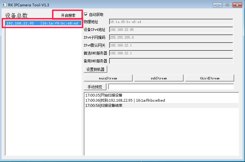
Use software to search for AI webcam device IP.
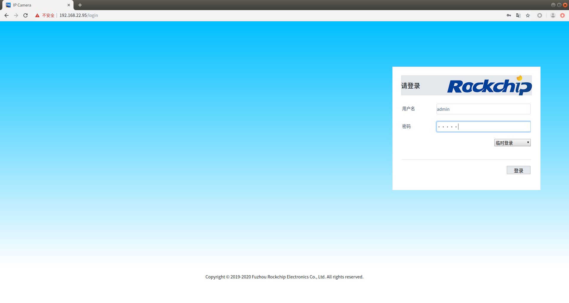
Enter the IP address of the device in the browser to enter the management page. The default account and password are
admin.
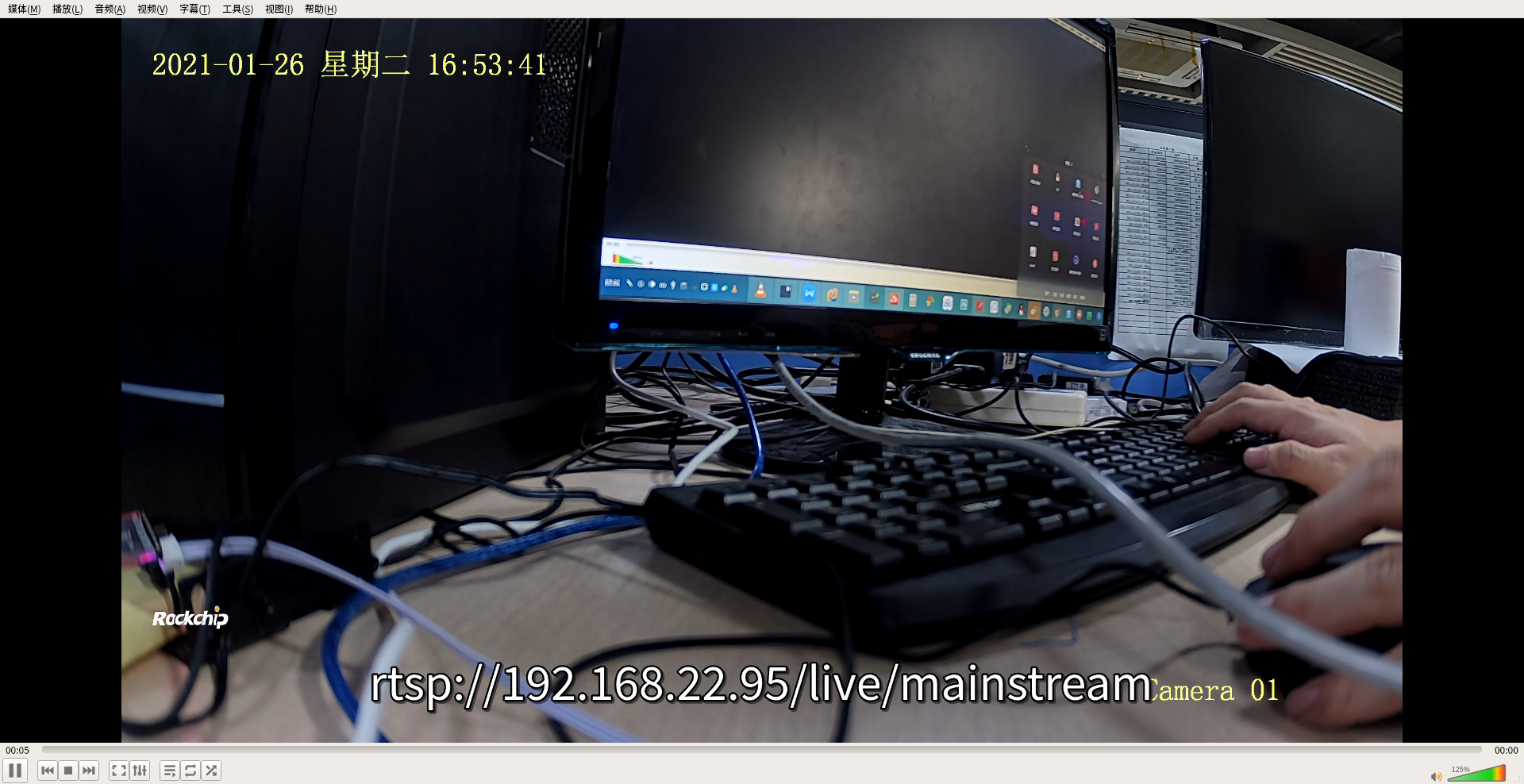
You can preview the camera using the RTSP Streaming Player.
If an external MIPI display is connected, a camera preview will appear on the display.
Quick Start
At present, the latest SDK of CORE-1126-JD4 has been adapted to quick start. Compile fastboot firmware options:
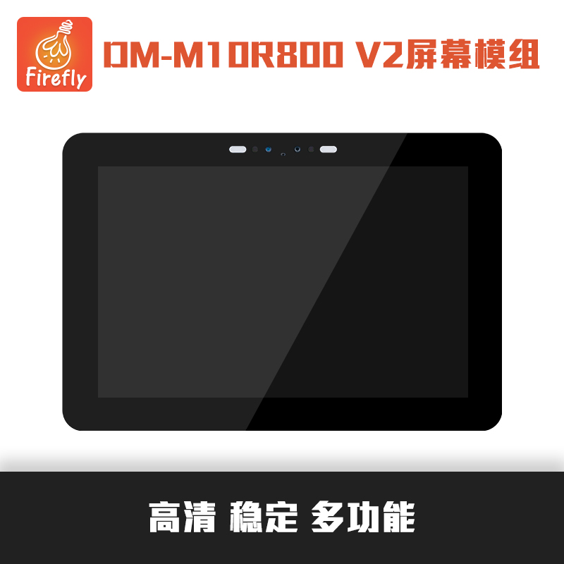
# Compile CORE-1126-JD4 V1.1 Quick Start Firmware. The adapted screen is the DM-M10R800 V2 screen module
./build.sh device/rockchip/rv1126_rv1109/aio-rv1126-jd4-BE-45-tb-v11.mk
After the quick boot firmware is activated, the MIPI DM-M10R800 V2 screen module can preview the camera image. If connected to the network, you can also preview the rtsp stream pushed by the camera. Linux PC preview command:
vlc rtsp://<device ip address>
Note: This quick boot firmware only applies to the core board of CORE-1126-JD4 V1.1 version. For the core board version, see the silkscreen on the hardware.
Debug Interface
The device can use USB cable, Network port or Serial port for debugging.
USB Cable Debugging
Hardware Wiring
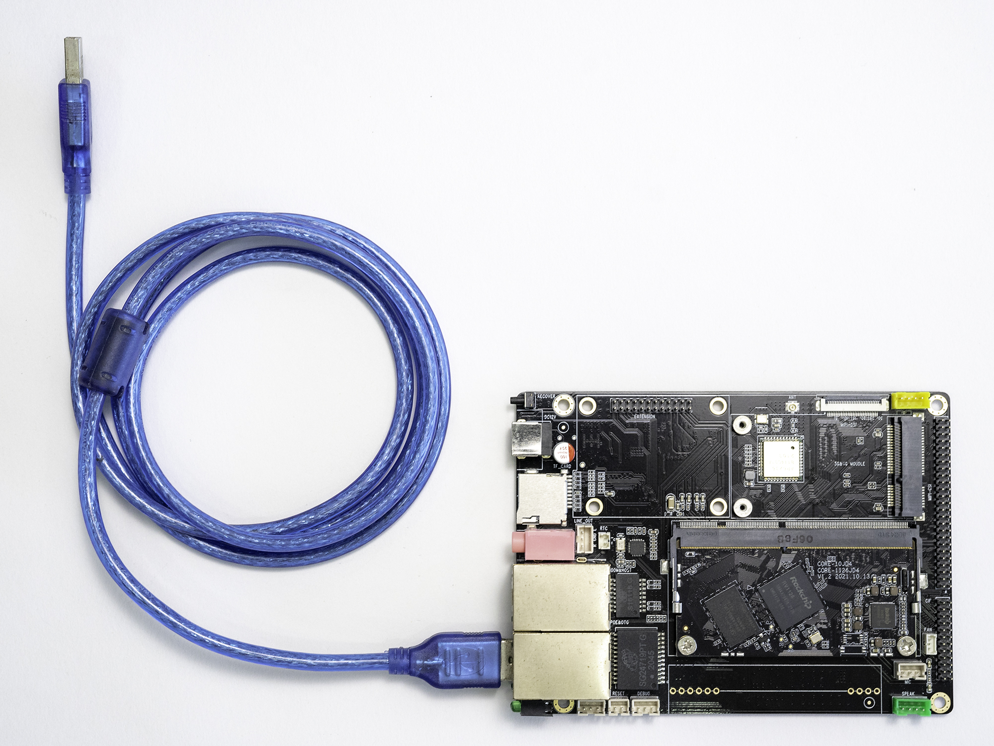
Prepare a male-to-male USB cable
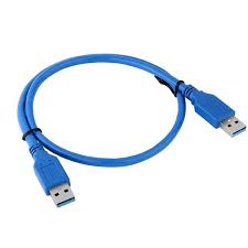
One end of the USB cable is connected to the USB port of the computer, and the other end is connected to the USB OTG debugging interface of the RV1126/RV1109 backplane. The wiring is as follows:
USB ADB Debugging
Use the network port cable to connect the device so that the device and the debugging host are in the same local area network.
Install ADB based on your system.
ADB Installation Under Windows:
Windows version: https://dl.google.com/android/repository/platform-tools-latest-windows.zip
Unzip to a custom directory
Press
windows + rto open the operation, entersysdm.cpland press Enter. Advanced–>Environment Variables–>System Variables–>Double-click Path –>NewExample: The settings are as shown in the figure below:
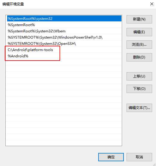
Note: The path needs to be changed to the custom directory you unzipped
Open the command prompt with administrator privileges, and the USB port of the computer is now connected to the USB debugging port of RV1126. Command prompt terminal enter
adb devices
C:\Users\lvsx>adb devices
* daemon not running; starting now at tcp:5037
* daemon started successfully
List of devices attached
d70a14329414b400 device
Use ADB for debugging.
adb shell
ADB Installation Under Ubuntu
sudo apt-get update
sudo apt-get install android-tools-adb
Verify installation:
lvsx@lvsx:~$ adb devices
* daemon not running; starting now at tcp:5037
* daemon started successfully
List of devices attached
d70a14329414b400 device
Use ADB for debugging.
adb shell
Network Port Debugging
Check the device IP through
RK_IPCamera_Tool. The RK_IPCamera_Tool tool can be downloaded from the resource download page.
Network ADB Debugging
Use network cable to connect to any network interface
The network cable is connected to the device network ADB.
adb connect 192.168.22.33
Use ADB for debugging.
adb shell
SSH Debugging
ssh to log in to the development board for debugging
The default account for firmware versions before September 2021 is: root, and the default password is: rockchip.
The default account for firmware versions after September 2021 is: root, and the default password is: firefly.
ssh root@192.168.22.33
The default account of Debian10 system is: firefly, and the default password is: firefly.
ssh firefly@192.168.22.33
Serial Debugging
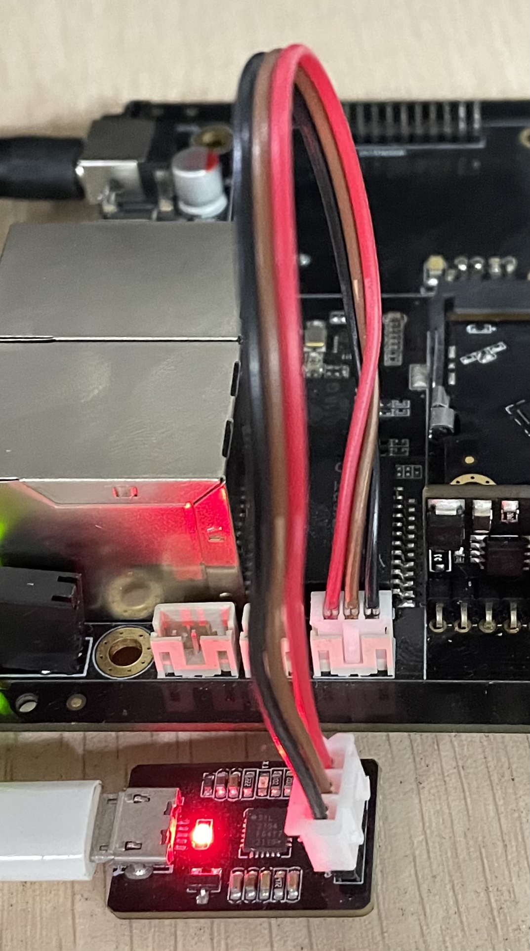
Prepare a USB to serial port module, and it is recommended to use Firefly’s serial port module.
Install the serial port module.
The USB serial port module connects the host USB port and the device serial port.
Set the baud rate to
1.5 M.According to your system download, install, open the serial port debugging tool supported by the system platform (Ubuntu recommends minicom, Window recommends using Use putty). If there is a serial port debugging tool with software and hardware flow control configuration items, please turn off this function.
The hardware connection of the serial port module of Firefly is shown in the figure:
Camera
RV1126/RV1109 core board + bottom board has been adapted to the matching 400W HDR high dynamic infrared enhanced wide-angle [OS04A10](https://item.taobao.com/item.htm?spm=a230r.1.14.1.422453ectFC4JL&id=648680997969&ns=1&abbucket= 18#detail) MIPI interface camera.
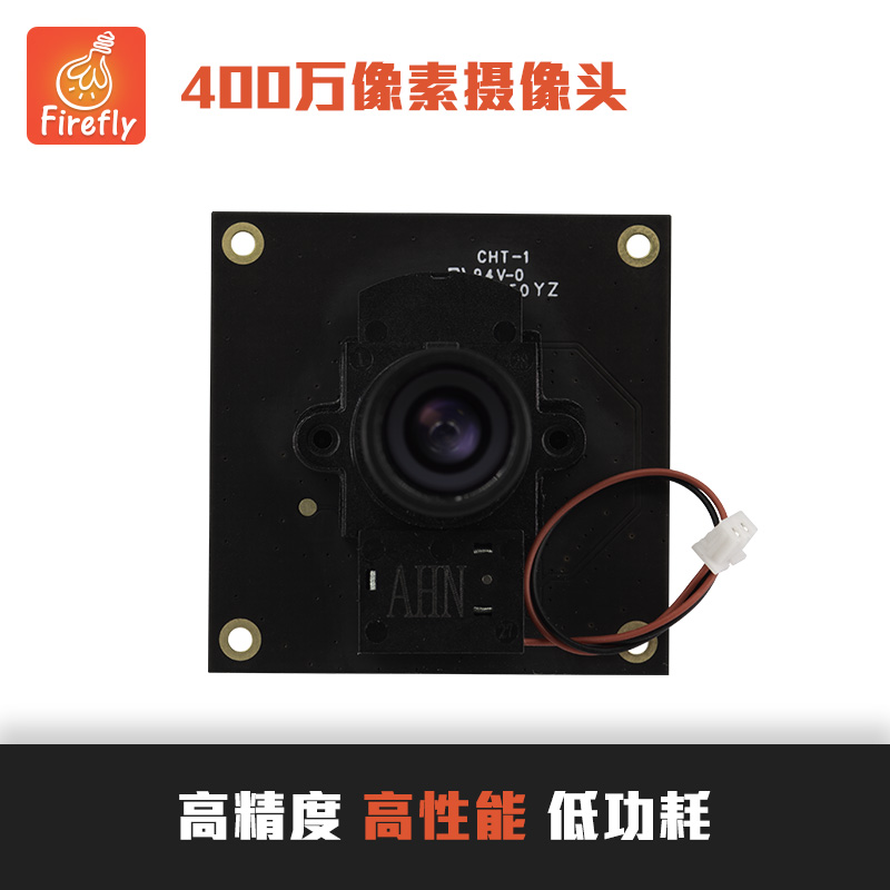
The connection method between the bottom plate and the camera is shown in the figure:
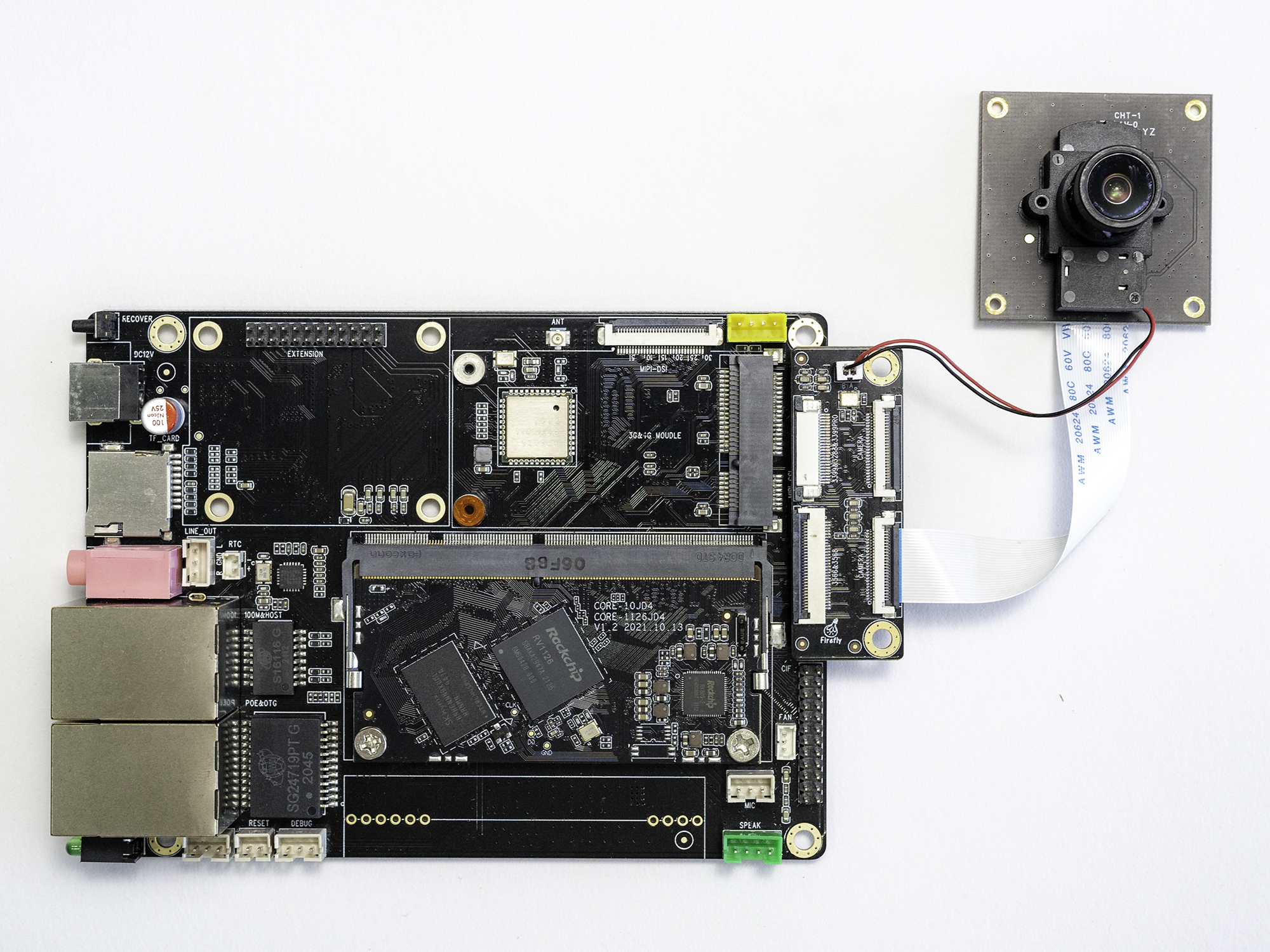
Note: The red and black lines on the camera are used as switching filters.
Command switch filter
# View SDK version
cd path-to-sdk/
realpath .repo/manifest.xml
If the SDK version obtained by the above command is rv1126_rv1109_linux_release_20220324_v2.2.5b.xml version and the date is 2022.03.24 or later, use the following command to perform IRCUT (filter switching):
# Close the filter
v4l2-ctl -d /dev/v4l-subdev5 --set-ctrl'band_stop_filter=0'

# Open the filter
v4l2-ctl -d /dev/v4l-subdev5 --set-ctrl'band_stop_filter=1'
If the SDK version obtained by the above command is not rv1126_rv1109_linux_release_20220324_v2.2.5b.xml version and the date is 2022.03.24 or later, use the following command to perform IRCUT (filter switching):
# Close the filter
v4l2-ctl -d /dev/v4l-subdev4 --set-ctrl'band_stop_filter=0'

# Open the filter
v4l2-ctl -d /dev/v4l-subdev4 --set-ctrl'band_stop_filter=1'
MIPI Screen
The matching screen for RV1126/RV1109 is [10.1 inch IPS full visual screen module MIPI multi-touch 1280x800 pixels](https://item.taobao.com/item.htm?spm=a1z10.5-cs.w4002-24147662620.19 .187cce42Nq5fe8&id=655100190974). The MIPI screen is shown in the figure:
The hardware connection between the baseboard and the MIPI screen is shown in the figure:
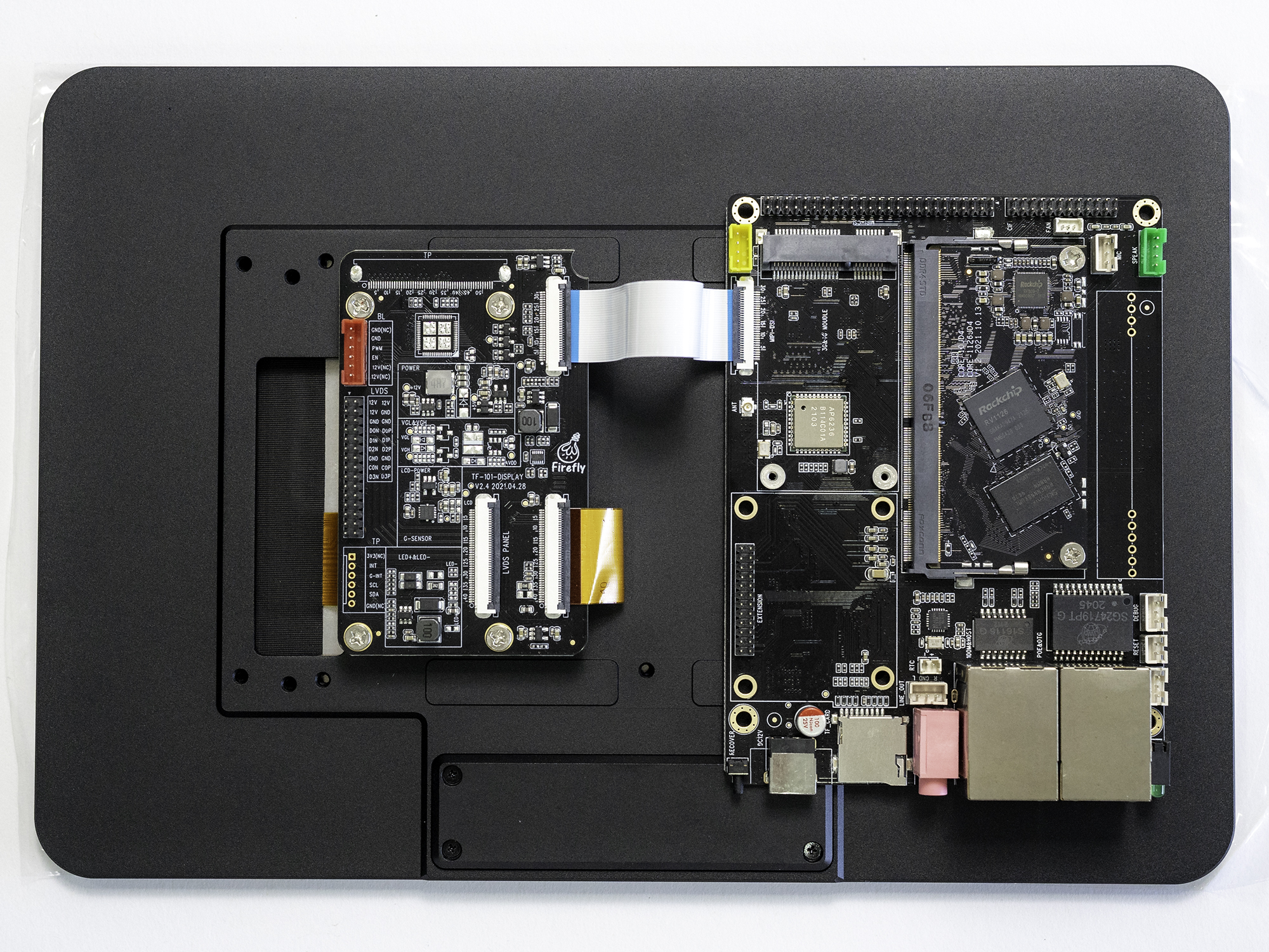
Note: The default public version firmware only displays the firefly LOGO icon when the baseboard is not connected to the camera. If the 0S04A10 camera is connected to the backplane, the camera preview interface will be displayed on the screen.