Use Peripherals
WiFi
* RV1109/RV1126 uses connman to manage WiFi by default and wpa_supplicant is the key process for WiFi:
ps -ef
#You can see the following two processes
connmand			 #It uses dbus to communicate with wpa_supplicant
wpa_supplicant -u  #Turns on support for dbus communication
Standard usage method: WiFi operation is carried out through the
RV1126/RV1109web interface, refer to the relevant documents ofRV1109/RV1126platform:Terminal simple test method is as follows:
killall ipc-daemon netserver
connmanctl
connmanctl> enable wifi
connmanctl> scan wifi #Allows multiple scans
connmanctl> scan wifi #Allows multiple scans
connmanctl> agent on
connmanctl> services
#List the scanned WiFi list
connmanctl>
	*AO yyz123
	NETGEAR75-5G	wifi_c0847daf6f42_4e45544745415237352d3547_managed_psk
	aaabbb			wifi_c0847daf6f42_616161626262_managed_psk
	HiWiFi-Free		wifi_c0847daf6f42_204869576946692d46726565_managed_none
	Fang-HiWiFi		wifi_c0847daf6f42_46616e672d486957694669_managed_psk
	yyz123				wifi_c0847daf6f42_79797a313233_managed_psk

connmanctl> connect wifi_c0847daf6f42_4e45544745415237352d3547_managed_psk
#If you want to connect to NETGEAR75-5G, then the connect parameter is wifixxx_psk
connmanctl>
Connected wifi_c0847daf6f42_4e45544745415237352d3547_managed_psk #This print will appear if the connection is successful
connmanctl> quit #Exit connection mode

ifconfig wlan0
#See the IP address of wlan0
If you don’t want to use connman and use the traditional
wpa_supplicant/wpa_cliapproach, do the following
#Close the default camera application
/oem/RkLunch-stop.sh
#Unlock peripheral devices
rfkill unblock all
killall wpa_supplicant
#Modify the wpa_supplicant.conf configuration file
vi /etc/wpa_supplicant.conf
#Replace SSID with WIFI name
#Replace PASSWORD with WiFi PASSWORD
wpa_supplicant -i wlan0 -c /etc/wpa_supplicant.conf -B & #WiFi WPA_Supplicant Background Connection
udhcpc -i wlan0 #Obtains IP address after successful WiFi connection
ping test whether wlan0 is connected to the external network
#The following results indicate a successful connection
[root@RV1126_RV1109:/]# ifconfig wlan0
wlan0     Link encap:Ethernet  HWaddr 10:2C:6B:7E:18:90
          inet addr:172.20.10.10  Bcast:172.20.10.15  Mask:255.255.255.240
          UP BROADCAST RUNNING MULTICAST  MTU:1500  Metric:1
          RX packets:54 errors:0 dropped:3 overruns:0 frame:0
          TX packets:128 errors:0 dropped:0 overruns:0 carrier:0
          collisions:0 txqueuelen:1000
          RX bytes:4803 (4.6 KiB)  TX bytes:16388 (16.0 KiB)
[root@RV1126_RV1109:/]# route add default gw 172.20.10.1 wlan0
[root@RV1126_RV1109:/]# ping -I wlan0 www.baidu.com
PING www.baidu.com (14.215.177.39) from 172.20.10.10 wlan0: 56(84) bytes of data.
64 bytes from 14.215.177.39 (14.215.177.39): icmp_seq=1 ttl=49 time=265 ms
64 bytes from 14.215.177.39 (14.215.177.39): icmp_seq=2 ttl=49 time=47.7 ms
64 bytes from 14.215.177.39 (14.215.177.39): icmp_seq=3 ttl=49 time=61.4 ms
64 bytes from 14.215.177.39 (14.215.177.39): icmp_seq=4 ttl=49 time=51.5 ms
64 bytes from 14.215.177.39 (14.215.177.39): icmp_seq=5 ttl=49 time=62.7 ms
4G Module
Check if the EC20 4G module kit has been loaded.
#The following 4 USB interfaces will appear after successful loading
ls /dev/ttyUSB*
/dev/ttyUSB0  /dev/ttyUSB1  /dev/ttyUSB2  /dev/ttyUSB3
If the load is not successful, check that the kernel has the following configuration turned on.
Symbol: USB_SERIAL_OPTION [=y]
Type  : tristate
Prompt: USB driver for GSM and CDMA modems
Location:
	-> Device Drivers
		-> USB support (USB_SUPPORT [=y])
			-> USB Serial Converter support (USB_SERIAL [=y])
Defined at drivers/usb/serial/Kconfig:558
Depends on: USB_SUPPORT [=y] && USB [=y] && USB_SERIAL [=y]
Selects: USB_SERIAL_WWAN [=y]
If the 4G module cannot be connected to the network, please check whether the following configuration is turned on in the kernel.
CONFIG_USB_USBNET
CONFIG_USB_NET_QMI_WWAN
Check whether the EC20 4G network card exists.
ifconfig wwan0
How to use EC20 4G module to access the Internet with a SIM card
# Download the ec20-armhf.tar.gz compressed package from the data download interface and copy it to the development board to decompress
# Need to replace the folder /ec20-armhf/usr/share/udhcpc/default.script with the system's /usr/share/udhcpc/default.script
# The results are as follows:
[root@RV1126_RV1109:/userdata/ec20-armhf]# quectel-CM &
[root@RV1126_RV1109:/userdata/ec20-armhf]# [04-20_14:27:04:405] Quectel_Linux_ConnectManager_SR01A01V21
[04-20_14:27:04:406] quectel-CM profile[1] = (null)/(null)/(null)/0, pincode = (null)
[04-20_14:27:04:407] Find qmichannel = /dev/cdc-wdm0
[04-20_14:27:04:407] Find usbnet_adapter = wwan0
[04-20_14:27:04:422] cdc_wdm_fd = 7
[04-20_14:27:05:422] QmiThreadSendQMITimeout pthread_cond_timeout_np=110, errno: 2 (No such file or directory)
[04-20_14:27:06:520] Get clientWDS = 19
[04-20_14:27:06:552] Get clientDMS = 1
[04-20_14:27:06:584] Get clientNAS = 3
[04-20_14:27:06:617] Get clientUIM = 1
[04-20_14:27:06:648] Get clientWDA = 1
[04-20_14:27:06:681] requestBaseBandVersion EC20CFDR02A07M4G  1  [Nov 10 2016 17:00:00]
[04-20_14:27:06:743] requestGetSIMStatus SIMStatus: SIM_READY
[04-20_14:27:06:777] requestGetProfile[1] cmnet///0
[04-20_14:27:06:808] requestRegistrationState2 MCC: 460, MNC: 0, PS: Attached, DataCap: LTE
[04-20_14:27:06:839] requestQueryDataCall ConnectionStatus: DISCONNECTED
[04-20_14:27:06:904] requestRegistrationState2 MCC: 460, MNC: 0, PS: Attached, DataCap: LTE
[04-20_14:27:07:447] requestSetupDataCall WdsConnectionIPv4Handle: 0x87205120
[04-20_14:27:07:513] requestQueryDataCall ConnectionStatus: CONNECTED
udhcpc: started, v1.27.2
Failed to kill daemon: No such file or directory
udhcpc: sending discover
udhcpc: sending select for 10.154.101.71
udhcpc: lease of 10.154.101.71 obtained, lease time 7200
Failed to kill daemon: No such file or directory
[04-20_14:27:07:729] deleting routers
[04-20_14:27:07:772] adding dns 221.179.38.7
[04-20_14:27:07:772] adding dns 120.196.165.7
[root@RV1126_RV1109:/userdata/ec20-armhf]#ifconfig wwan0
wwan0     Link encap:UNSPEC  HWaddr 00-00-00-00-00-00-00-00-00-00-00-00-00-00-00-00
          inet addr:10.154.101.71  P-t-P:10.154.101.71  Mask:255.255.255.240
          UP POINTOPOINT RUNNING NOARP MULTICAST  MTU:1500  Metric:1
          RX packets:2 errors:0 dropped:0 overruns:0 frame:0
          TX packets:2 errors:0 dropped:0 overruns:0 carrier:0
          collisions:0 txqueuelen:1000
          RX bytes:612 (612.0 B)  TX bytes:656 (656.0 B)
Sound Card
EarPhone && Speak
Both EarPhone and Speak are dual-channel interfaces
Use the aplay command to play audio in wav format
#path-to indicates the absolute path to store the audio
aplay /path-to/audio-name.wav
Mic
Mic is off by default. You need to turn it on to use it.
#The command sets the default recording sound card channel.
amixer cset numid=2,iface=MIXER,name='Capture MIC Path' 1

#Set the default recording sound card channel.
alsamixer
#Set the Capture MIC Path to Main MIC
Mic records audio
arecord -l											#View all available MIC devices.
arecord -Dhw:0,0 -f cd -d 10 /path-to/audio.wav	#Select the sound card and record audio.
#Note: Mic only supports mono recording
MIPI-CSI
MIPI-CSI Camera requires purchase of adapter board
v4l2 interface to operate MIPI-CSI camera
#If the probe is successful, there will be video and media devices in /dev/.
#There may be multiple /dev/video devices in the system. You can find the registered video node of RKISP through /sys.
#It corresponds to the rkispp_scale0 node, the following print is /dev/video19
[root@RV1126_RV1109:/]# grep '' /sys/class/video4linux/video*/name
/sys/class/video4linux/video0/name:stream_cif_mipi_id0
/sys/class/video4linux/video1/name:stream_cif_mipi_id1
/sys/class/video4linux/video10/name:rkisp_rawwr3
/sys/class/video4linux/video11/name:rkisp_rawrd0_m
/sys/class/video4linux/video12/name:rkisp_rawrd2_s
/sys/class/video4linux/video13/name:rkisp_rawrd1_l
/sys/class/video4linux/video14/name:rkisp-statistics
/sys/class/video4linux/video15/name:rkisp-input-params
/sys/class/video4linux/video16/name:rkisp-mipi-luma
/sys/class/video4linux/video17/name:rkispp_input_image
/sys/class/video4linux/video18/name:rkispp_m_bypass
/sys/class/video4linux/video19/name:rkispp_scale0
/sys/class/video4linux/video2/name:stream_cif_mipi_id2
/sys/class/video4linux/video20/name:rkispp_scale1
/sys/class/video4linux/video21/name:rkispp_scale2
/sys/class/video4linux/video22/name:rkispp_iqtool
/sys/class/video4linux/video23/name:rkispp_input_params
/sys/class/video4linux/video24/name:rkispp-stats
/sys/class/video4linux/video3/name:stream_cif_mipi_id3
/sys/class/video4linux/video4/name:rkcif-mipi-luma
/sys/class/video4linux/video5/name:rkisp_mainpath
/sys/class/video4linux/video6/name:rkisp_selfpath
/sys/class/video4linux/video7/name:rkisp_rawwr0
/sys/class/video4linux/video8/name:rkisp_rawwr1
/sys/class/video4linux/video9/name:rkisp_rawwr2

#v4l2-ctl grabs a frame and saves it in /tmp/cif.out
# /dev/video19 is not fixed, it needs to be configured according to the above matching to get the corresponding node
#You need to close the default camera application before grabbing pictures
/oem/RkLunch-stop.sh
/oem/usr/bin/dbserver &
/usr/bin/ispserver &

#After opening dbserver and ispserver, you can take a screenshot
v4l2-ctl -d /dev/video19 \
--set-fmt-video=width=1920,height=1080,pixelformat=NV12 \
--stream-mmap=3 \
--stream-skip=3 \
--stream-to=/tmp/cif.out \
--stream-count=1 \
--stream-poll

#v4l2-ctl grabs 10 frames of continuous images as a video and saves it in /tmp/test.yuv
v4l2-ctl -d /dev/video19  --try-fmt-video=width=1920,height=1080,pixelformat=NV12 --stream-mmap=3 --stream-to=/tmp/test.yuv --stream-count=10 --stream-poll

#Linux PC uses ffplay to play captured videos
ffplay -f rawvideo -video_size 1920x1080 -pix_fmt nv12 test.yuv
Access network code streams Access using a player that supports RTSP or RTMP, for example (VLC player).
RTSP access address:
rtsp://Device IP address/live/mainstream
rtsp://Device IP address/live/substream
rtsp://Device IP address/live/thirdstream
RTMP access address:
rtmp://Device IP address:1935/live/substream
Example: VLC player previews an RTSP stream
#Note: VLC player needs to be installed
vlc rtsp://Device IP address/live/mainstream
Access device information via web pages Open a Web browser (Chrome is recommended) to access the following address:
http://Device IP address
#Username and password are admin.
See Rockchip_Instructions_Linux_Web_Configuration_CN.pdf under SDK directory docs for detailed instructions on the web side.
MIPI-DSI
Screen turn
#Specifies the Qt output platform and turns the screen 90° clockwise
export QT_QPA_PLATFORM=linuxfb:rotation=90
If the screen appears splashed, or not displayed. Please check whether there is any problem with the LCD wiring. Replacing the short wiring with high quality material can solve the problem of the splashy screen.
LED
Select GPIO port, modify kernel device tree, and add custom LED lamp device node.
vim sdk/kernel/arch/arm/boot/dts/rv1126-firefly-ai-cam.dts
# Refer to the following configuration to add the LED node.
leds {
    compatible = "gpio-leds";

	work {
        label = "firefly:blue:power";
        linux,default-trigger = "ir-power-click";
        gpios = <&gpio0 RK_PA4 GPIO_ACTIVE_HIGH>;
        pinctrl-names = "default";
        pinctrl-0 = <&led_power>;
        default-state = "on";
	};
    user {
        label = "firefly:yellow:user";
        linux,default-trigger = "ir-user-click";
        gpios = <&gpio0 RK_PC0 GPIO_ACTIVE_HIGH>;
        pinctrl-names = "default";
        pinctrl-0 = <&led_user>;
        default-state = "on";
	};
};

# Pinctrl needs to add GPIO multiplexing control
leds {
	led_power: led-power {
            rockchip,pins = <0 RK_PA4 RK_FUNC_GPIO &pcfg_pull_none>;
        };

        led_user: led-user {
            rockchip,pins = <0 RK_PC0 RK_FUNC_GPIO &pcfg_pull_none>;
        };
};
# Compile and upgrade the kernel after the modification.
To control the LED
echo 1 > /sys/class/leds/firefly:yellow:user/brightness # bright
echo 0 > /sys/class/leds/firefly:yellow:user/brightness # destroy
POE
The network port where
POEfunction can be added is1000M, as shown in the figure below: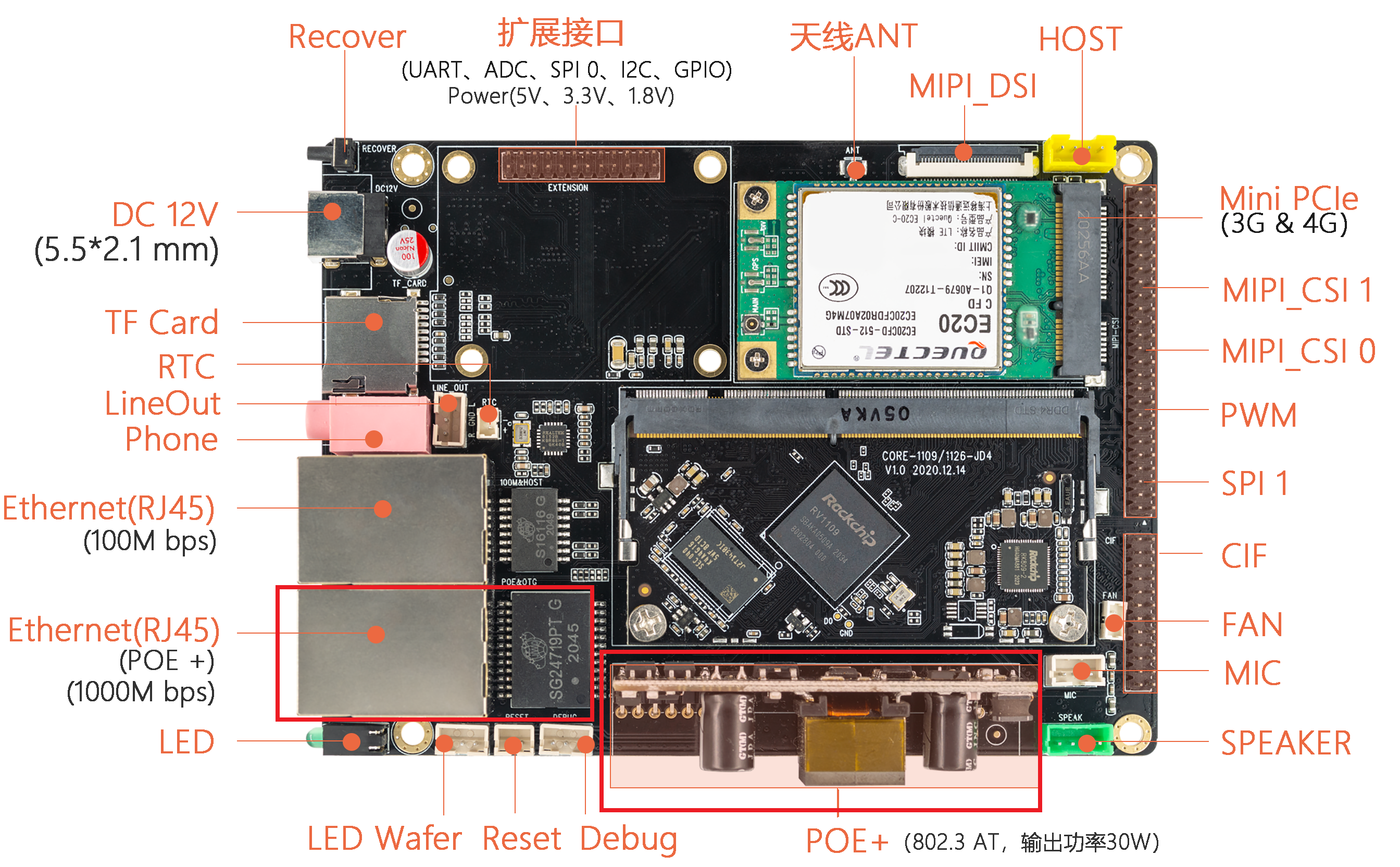 The
The POEmodule needs to be connected to thePOEinterface of the bottom plate
#Check whether 1000M POE port exists
ifconfig eth1