5. LED
5.1. Introduction
LEDs can be controlled by using the LED device subsystem or by directly operating GPIO.
5.2. Controlling LEDs by device
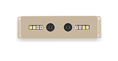
Linux has its own LED subsystem for LED devices. In CAM-C1109S2U, LEDs are configured as LED class devices.You can control them via /sys/class/leds/.
IR: IR infrared fill light status
RGB: White LED fill light status
You can change the behavior of each LED by using the echo command to write command to its brightness property:
IR infrared fill light:
echo 77 > /sys/class/leds/PWM-IR/brightness # Infrared fill light on
echo 0 > /sys/class/leds/PWM-IR/brightness  # Infrared fill light off
White LED fill light:
echo 15 > /sys/class/leds/PWM-RGB/brightness # White LED fill light on
echo 0 >  /sys/class/leds/PWM-RGB/brightness # White LED fill light off
Note:
Since the IR fill light and white LED fill light of CAM-C1109S2U are driven by PWM, you can adjust the PWM duty cycle to adjust the brightness of the light. echo input a value in the range of 0 ~ 255 to control the brightness of the light.
Note:
The IR fill light is a high-power component. It is the main power source of the device. Since the CAM-C1109S2U device is relatively compact, setting the IR fill light brightness too high will increase the device power consumption, causing the device to heat up severely. Excessive device temperature will cause performance degradation.
Since CAM-C1109S2U has only one TYPE-C power port. Setting the IR fill light brightness too high will increase the current supply demand. If the power is supplied by the USB port on the front of a laptop or PC, it is easy to have insufficient power supply current. In this case of insufficient power supply current, the device may restart or disconnect from the host computer.
Solutions for different application scenarios:
If it is a Facial_Gate application scenario, and data communication with the host computer is not required via USB, a higher power supply can be used to power the device. For example, a 5V 2A or 5V 3A power adapter can be used to power the device.
If data communication with the host computer is required via USB, use a USB HUB that can be connected to an external power supply to power the CAM-C1109S2U device.
5.3. Using trigger control LED
Trigger contains a variety of ways to control the LED, here with two examples to illustrate.
Simple trigger LED
Complex trigger LED
For more information, please read the document leds-class.txt.
First of all, we need to know how many LED definition, while the corresponding property of the LED is.
Board:sdk/kernel/arch/arm/boot/dts/rv1109-firefly-ai-cam.dtsi:
pwmleds {
	compatible = "pwm-leds";

	pwmi_ir {
		label = "PWM-IR";
		pwms = <&pwm7 0 25000 0>;
		max-brightness = <255>;
	};

	pwmi_rgb {
		label = "PWM-RGB";
		pwms = <&pwm2 0 25000 0>;
		max-brightness = <255>;
		init-brightness = <15>;
	};
};
Note: The value of compatible must match the one in drivers/leds/leds-gpio.c.
5.3.1. Complex trigger LED
The following is the trigger mode control LED complex example, timer trigger is to let the LED to achieve constant light off effect.
We need to configure the timer trigger on the kernel.
In the kernel path using make menuconfig, in accordance with the following method to chose timer trigger driver.
Device Drivers
--->LED Support
   --->LED Trigger support
      --->LED Timer Trigger
Save the configuration and compile the kernel, the kernel.img burn CAM-C1109S2U board. We can use the serial input command, you can see the blue light non-stop interval flashing.
# IR fill light flashes
echo "timer" > /sys/class/leds/PWM-IR/trigger

# White LED fill light flashes
echo "timer" > /sys/class/leds/PWM-RGB/trigger
The user can also use the cat command to get the available values for the trigger:
$ cat /sys/class/leds/PWM-RGB/trigger
none rfkill-any rfkill-none mmc0 [timer] oneshot heartbeat default-on