9. UART Use
9.1. Introduction
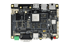
AIO-3288C development board supports the function of SPI bridging/expanding 4 function-enhancing serial ports (UART), which are RS232, RS485 and 1 debug serial port UART2 respectively.
Of which: UART2 is TTL level interface, RS232 is RS232 level interface, RS485 is RS485 level interface.
Note: RS232 needs to use RS232 crossover cable to use, otherwise rx and tx will have unsuccessful transmission and reception.
9.2. Debug method
The kernel has enabled these serial ports in default, the software nodes corresponding to hardware interface are:
RS485: /dev/ttyS1
RS232: /dev/ttyS3
UART2: /dev/ttyS2
The user can use different USB to serial port adapters of the host computer to transmit/receive data to/from the serial port of development board according to different ports, for example, the debugging steps of RS485 are as follows:
9.2.1. Connect hardware
Connect the A, B and GND pins of RS485 on development board to the corresponding pins of serial port adapter of host computer (USB to 485 to serial port module) respectively.
9.2.2. Turn on the serial port terminal of host computer
Enable Kermit on the terminal and set Baud rate:
$ sudo kermit
C-Kermit> set line /dev/ttyUSB*
C-Kermit> set speed 9600
C-Kermit> set flow-control none
C-Kermit> connect
/dev/ttyUSB*is the device file of USB to serial port adapter
9.2.3. Send data
The device file of RS485 is /dev/ttyS1. Run the following command on the device:
echo firefly RS485 test… > /dev/ttyS1
The serial terminal in host computer can receive the character string “firefly RS485 test…”
9.2.4. Receive data
Firstly run the following command on the device:
cat /dev/ttyUSB*
Then, input the character string “Firefly RS485 test…” at the serial terminal in host computer. You can see the same character string on the device.
9.2.4.1. Attention
UART2 can test rx/tx short connection for loop communication. RS232 can only test communication with other hosts,it does not support loop sending and receiving data because of hardware.
