3. PCIe
3.1. Introduction
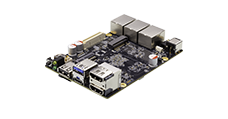
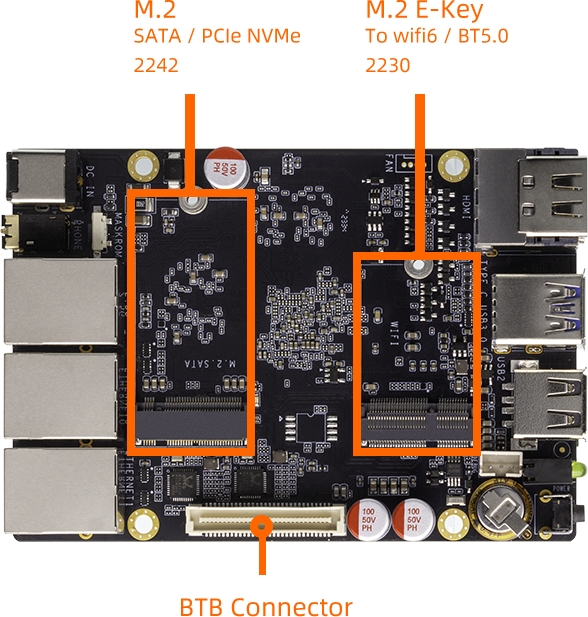
There is one PCIe3.0 x 4 interface and PCIe2.0 x 2 on the ROC-RK3588-RT development board, as shown in the figure:
On board default support for M.2 SATA and PCIE WiFi/BT module
3.2. Software configuration
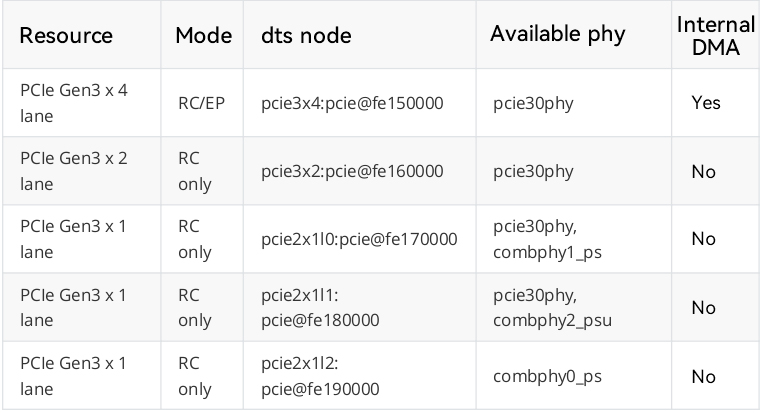
The available hardware resources of RK3588 PCIe and the corresponding relationship between the pcie controller node and PHY node on the software are shown in the figure:
3.2.1. DTS configuration
Generally, configure the power supply pin and reset pin in DTS according to the schematic diagram, and select the correct pcie controller node and PHY node to enable.
There is the following configuration about 4 x 2.5G mesh EXT board in kernel-5.10/arch/arm64/boot/dts/rockchip/roc-rk3588-rt-ext.dtsi:
/* pcie3.0 x 4 Lane */
&pcie30phy {
    rockchip,pcie30-phymode = <PHY_MODE_PCIE_NABIBI>;
    status = "okay";
};

&pcie3x2 {
        num-lanes = <1>;
        reset-gpios = <&gpio3 RK_PD4 GPIO_ACTIVE_HIGH>;
        vpcie3v3-supply = <&vcc3v3_pcie30>;
    rockchip,skip-scan-in-resume;
    rockchip,perst-inactive-ms = <500>;
    status = "okay";
};
&pcie3x4 {
        num-lanes = <1>;
        reset-gpios = <&gpio4 RK_PB6 GPIO_ACTIVE_HIGH>;
        vpcie3v3-supply = <&vcc3v3_pcie30>;
    rockchip,skip-scan-in-resume;
    rockchip,perst-inactive-ms = <700>;
    status = "okay";
};

&vcc3v3_pcie30{
        gpios = <&gpio1 RK_PB2 GPIO_ACTIVE_HIGH>;
        regulator-always-on;
        startup-delay-us = <5000>;
        status = "okay";
};
pcie30phy:PHY node
pcie3x2:pcie3x2 controller node
pcie3x4:pcie3x4 controller node
reset-gpios:reset pin properties
vcc3v3_pcie30:power supply pin node