11. UART
11.2. DTS configuration
File path kernel-5.10/arch/arm64/boot/dts/rockchip/roc-rk3588-pc.dtsi
/* uart7 */
&uart7 {
	status = "okay";
	pinctrl-0 = <&uart7m0_xfer>;
};
After configuring the serial port, the hardware interface corresponds to the node on the software as
UART7: /dev/ttyS7
11.3. Send and receive verification
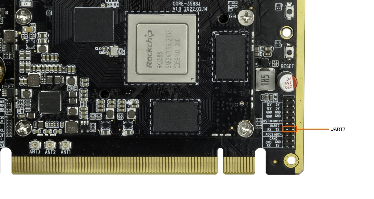
The easiest way is to short the UART7 TX RX pins, then use the command to execute the command on the debug serial port or ADB
busybox stty -echo -F /dev/ttyS7 # Turn off display back
cat /dev/ttyS7 & # get /dev/ttyS7 input string in the background
echo "firefly uart test..." > /dev/ttyS7 # Input string
The final debug serial terminal can receive the string “firefly uart test…”