1. ADC
1.1. Introduction
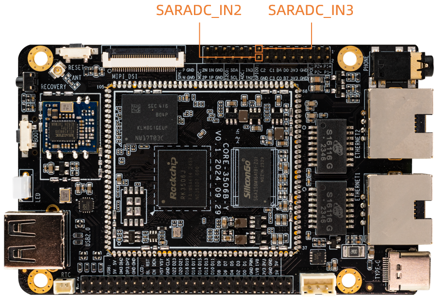
The ROC-RK3506J-CC development board has two kinds of AD interface, respectively: Temperature Sensor and Successive Approximation Register. Among them:
TS-ADC (Temperature Sensor): Supports one channel.
SAR-ADC (Successive Approximation Register): Supports eight-channel single-ended 10-bit SAR-ADC, The maximum conversion rate is 1MS/s.
The kernel uses the industrial I/O subsystem to control the ADC, which is mainly designed for AD conversion or DA conversion sensor. The following is an example of SAR-ADC using ADC fan to introduce the basic configuration method of ADC.
1.3. DTS configuration
1.3.1. Configure DTS nodes
The SAR-ADC nodes of ROC-RK3506J-CC defined in kernel/arch/arm/boot/dts/rk3502.dts file, as showm below:
saradc: adc@ff4e8000 {
	compatible = "rockchip,rk3506-saradc", "rockchip,rk3562-saradc";
	reg = <0xff4e8000 0x8000>;
	interrupts = <GIC_SPI 57 IRQ_TYPE_LEVEL_HIGH>;
	#io-channel-cells = <1>;
	clocks = <&cru CLK_SARADC>, <&cru PCLK_SARADC>;
	clock-names = "saradc", "apb_pclk";
	resets = <&cru SRST_P_SARADC>;
	reset-names = "saradc-apb";
	status = "disabled";
};
1.4. Drive instructions
1.4.1. Get AD channel
struct iio_channel *chan;                    #Defines the IIO channel structure
chan = iio_channel_get(&pdev->dev, NULL);    #Get AD channel structure
Note: iio_channel_get gets the IIO channel structure through the parameter pdev passed in by the probe function. The probe function is as follows:
static int XXX_probe(struct platform_device *pdev);
1.4.2. Read the original data collected by AD
int val,ret;
ret = iio_read_channel_raw(chan, &val);
Call the iio_read_channel_raw function to read the raw data collected by AD and store it in val.
1.4.3. Calculate the collected voltage
The standard voltage is used to convert the value of AD to the voltage value required by the user. The calculation formula is as follows:
Vref / (2^n-1) = Vresult / raw
Note:
Vref is the standard voltage
n is the number of bits converted to AD
Vresult is the collection voltage required by the user
raw is the original data that AD collects
For example, the standard voltage is 1.8V, the collection bits of AD is 10, and the original data collected by AD is 568, then:
Vresult = (1800mv * 568) / 1023;
1.5. Interface specification
struct iio_channel *iio_channel_get(struct device *dev, const char *consumer_channel);
Function : Gets the iio channel description.
Parameters :
dev: Using the device description pointer of this channel.
consumer_channel: The IIO channel description pointer used by the device.
void iio_channel_release(struct iio_channel *chan);
Function : Release the channel obtained by the
iio_channel_getfunction.Parameters :
chan :The channel description pointer to be released.
int iio_read_channel_raw(struct iio_channel *chan, int *val);
Function : Read the original data collected by chan channel AD.
Parameters :
chan:Collection channel pointer to read.
val:The pointer to the result of reading.
1.6. Debug method
1.6.1. Gets all ADC values
There is a convenient way to query the value of each SARADC:
cat /sys/bus/iio/devices/iio\:device0/in_voltage*_raw
1.7. FAQs
1.7.1. Follow the steps above to apply for SARADC. Why is there an application error?
When the driver needs to get the ADC channel to use, it needs to control the load time of the driver, which must be after saradc initialization. Saradc uses module_platform_driver() for platform device driver registration and ultimately calls module_init(). Therefore, the driver loading function of the user only needs to use one with lower priority than module_init(), such as late_initcall(), so as to ensure that the loading time of the driver is later than the initialization time of saradc and avoid errors.