LED
Introduction
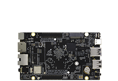
There are 2 LEDs on the ROC-RK3399-PC Pro development board, as the following table shows:
| LED | GPIO ref. | GPIO number |
|---|---|---|
| BLUE | GPIO2_D3 | 91 |
| RED | GPIO0_B5 | 13 |
Both LEDs can be controlled by using the LED device subsystem or by directly operating GPIO.
Controlling LEDs by device
Linux has its own LED subsystem for LED devices. In ROC-RK3399-PC Pro, 2 LEDs are configured as LED class devices.
You can control them via /sys/class/leds/.
The default status of the two on-board leds are:
Blue: Turn on after the system powers on.
Yellow: defined by user.
You can change the behavior of each LED by using the echo command to write command to its brightness property:
root@rk3399_firefly_box:~ # echo 0 >/sys/class/leds/firefly:blue:power/brightness  //Blue led off
root@rk3399_firefly_box:~ # echo 1 >/sys/class/leds/firefly:blue:power/brightness  //Blue led on
Using trigger control LED
Trigger contains a variety of ways to control the LED, here with two examples to illustrate.
Simple trigger LED
Complex trigger LED
For more information, please read the document leds-class.txt.
First of all, we need to know how many LED definition, while the corresponding property of the LED is.
Define LED node in file kernel/arch/arm64/boot/dts/rockchip/rk3399-firefly-port.dtsi
leds {
       compatible = "gpio-leds";
       power_led: power {
           label = "firefly:blue:power";
           linux,default-trigger = "ir-power-click";
           default-state = "on";
           gpios = <&gpio2 27 GPIO_ACTIVE_HIGH>;
           pinctrl-names = "default";
           pinctrl-0 = <&led_power>;
       };
       user_led: user {
           label = "firefly:yellow:user";
           linux,default-trigger = "ir-user-click";
           default-state = "off";
           gpios = <&gpio0 13 GPIO_ACTIVE_HIGH>;
           pinctrl-names = "default";
           pinctrl-0 = <&led_user>;
       };
   };
Note: The value of compatible must match the one in drivers/leds/leds-gpio.c.
Simple trigger LED
It is a simple trigger mode to control LEDs, as follows on the default open yellow LED. And ROC-RK3399-PC Pro’s yellow LED will be turned on after boot.
(1) Defined LED trigger In the kernel/drivers/leds/trigger/led-firefly-demo.c add the following:
DEFINE_LED_TRIGGER(ledtrig_default_control);
(2) Register the trigger.
led_trigger_register_simple("ir-user-click", &ledtrig_default_control);
(3) Control the LED.
led_trigger_event(ledtrig_default_control, LED_FULL); #yellow led on
(4)Enable LED demo.
led-firefly-demo is disabled in default,if you need to open the demo drive can use the following patch:
--- a/kernel/arch/arm64/boot/dts/rockchip/rk3399-firefly-demo.dtsi
+++ b/kernel/arch/arm64/boot/dts/rockchip/rk3399-firefly-demo.dtsi
@@ -52,7 +52,7 @@
            led_demo: led_demo {
-                status = "disabled";
+                status = "okay";
                 compatible = "firefly,rk3399-led";
                 };
Complex trigger LED
The following is the trigger mode control LED complex example, timer trigger is to let the LED to achieve constant light off effect.
We need to configure the timer trigger on the kernel.
In the kernel path using make menuconfig, in accordance with the following method to chose timer trigger driver.
Device Drivers
--->LED Support
   --->LED Trigger support
      --->LED Timer Trigger
Save the configuration and compile the kernel, the kernel.img burn ROC-RK3399-PC Pro board. We can use the serial input command, you can see the blue light non-stop interval flashing.
echo "timer" > sys/class/leds/firefly\:blue\:power/trigger
The user can also use the cat command to get the available values for the trigger:
root@rk3399_firefly_box:/ # cat sys/class/leds/firefly\:blue\:power/trigger
none rc-feedback test_ac-online test_battery-charging-or-full test_battery-charging
test_battery-full test_battery-charging-blink-full-solid test_usb-online mmc0 mmc1
ir-user-click [timer] heartbeat backlight default-on rfkill0 mmc2 rfkill1 rfkill2
