UART
Introduction
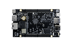
In order to facilitate user development, roc-3399-pc-plus introduces two channels such as UART0 and UART4 (reuse with SPI1) on the double-row extension interface of the board.
UART0 and UART4 are TTL level interfaces.
UART0 UART4 maximum support baud rate 691200.
Each subchannel has a 256-byte FIFO that can receive/send independently. FIFO interrupt can be programmed to trigger according to user needs
With a sub-serial port to receive FIFO timeout interrupt
Support initial bit error detection
DTS
In the case of UART0 configuration, the device tree opens UART0 nodes by default.
&uart0 {
    status = "okay";
};
Debug method
After the serial port is configured, the corresponding nodes of the hardware interface on the software are:
UART0:/dev/ttyS0
(1) The connection of hardware
Connect the TX of UART0 with the RX port and the RX and TX of the USB adapter.
(2) Open the serial terminal of the host
Open kermit at the terminal and set the baud rate:
$ sudo kermit
C-Kermit> set line /dev/ttyUSB0
C-Kermit> set speed 115200
C-Kermit> set flow-control none
C-Kermit> connect
The /dev/ttyUSB0 is the device file for the USB adapter
(3) Send data
The device file for UART0 is /dev/ttys0.Run the following commands on the device:
echo firefly test... > /dev/ttyS0
The serial terminal in the host receives the string “firefly test…”
(4) Receive data
First run the following command on the device:
cat /dev/ttyS0
Then enter the string “firefly test…”, the device side will see the same string.
Note
GPS wireless module will occupy UART0, so GPS function should be disabled when using UART0 as ordinary serial port.
