1. 4G
IHC-3308GW has single wifi version and wifi+4g version, please confirm that the machine used is equipped with 4G module.
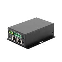
Resolution method: Check the number of antennas, if there is only one antenna interface, it is the single wifi version. If there are two antenna interfaces, it is the wifi+4g version.
The 4G module used is EC200S-CN, for Buildroot or Ubuntu system, after power on, the system will automatically dial
1.1. SIM card connection

1.2. 4G antenna connection

1.3. Manual AT command dial-up networking
If the system cannot dial normally, you can use AT commands to troubleshoot the problem manually.
Confirm whether the
EC200S-CNmodule starts normally, and theusb0network card corresponds to theEC200S-CNmodule
#ifconfig usb0
usb0 Link encap:Ethernet HWaddr AE:0C:29:A3:9B:6D
          inet addr:192.168.43.100 Bcast:192.168.43.255 Mask:255.255.255.0
          inet6 addr: fe80::ed5d:84b6:c27c:3825/64 Scope:Link
          UP BROADCAST RUNNING MULTICAST MTU:1500 Metric:1
          RX packets:18 errors:0 dropped:0 overruns:0 frame:0
          TX packets:39 errors:0 dropped:0 overruns:0 carrier:0
          collisions:0 txqueuelen:1000
          RX bytes: 3456 (3.3 KiB) TX bytes: 3811 (3.7 KiB)
Configure serial port properties
If it is an
Ubuntusystem, it needs to be configured# stty -F /dev/ttyUSB2 icrnl opost onlcr icanon echo echoeQuery module status
# cat /dev/ttyUSB2 &
# echo AT+QCFG="usbnet" > /dev/ttyUSB2
If it returns
+QCFG: "usbnet",1, that isECMstatusModule is configured to
ECMNIC statusecho AT+QCFG="usbnet",1 > /dev/ttyUSB2
Dial
echo AT+QNETDEVCTL=1,1,1 > /dev/ttyUSB2
ping external network

Other AT commands
disconnect dial
echo AT+QNETDEVCTL=0,1,1 > /dev/ttyUSB2
Check the strength of the antenna signal, return the value “0-31,99”, try to ensure that the signal strength is “26-31,99”
echo "AT+CSQ" > /dev/ttyUSB2
Check whether the sim card or IoT card is inserted, and return to READY normally
echo "AT+CPIN?" > /dev/ttyUSB2
Check the operator, such as China Unicom CHN-UNICOM, mobile “CHINA MOBILE”
echo "AT+COPS?" > /dev/ttyUSB2
Check whether the traffic service of the sim card is normal
echo "AT+CGATT?" > /dev/ttyUSB2
Return +CGATT: 1 means attached, +CGATT: 0 means detached, when returning +CGATT: 0, please check whether the traffic service of the card is normal
2. Uart
The expansion board expands multiple serial ports for use, including 3 RS485 and 1 RS232.
The kernel already supports the above serial port functions by default. The device files corresponding to each serial port are as follows:
RS485_1: /dev/ttysWK0
RS485_2: /dev/ttysWK1
RS485_3: /dev/ttysWK2
RS232 : /dev/ttysWK3
Take RS485_1 as an example:
connect
Connect the A and B pins of RS485_1 to the A and B pins of the host serial adapter (USB to 485 to serial port module) respectively.
Open the serial terminal of the host
Open kermit in the terminal and set the baud rate:
$ sudo kermit
C-Kermit> set line /dev/ttysWK0
C-Kermit> set speed 9600
C-Kermit> set flow-control none
C-Kermit > connect
/dev/ttyUSB0 is the device file of the USB-to-serial adapter recognized by the host.
send data
Run the following command on the device:
echo "Firefly RS485 test..." > /dev/ttysWK0
The serial terminal in the host can receive the string “Firefly RS485 test…”.
Receive data
First run the following command on the device:
cat /dev/ttysWK0
Then enter the string “Firefly RS485 test…” in the serial terminal of the host, and the same string can be seen on the device side.
3. CAN
connect
Just connect the CANH, CANL of the device and the CANH, CAHL of the communication terminal correspondingly.
send data
ip link set can0 down
ip link set can0 type can bitrate 250000
ip link set can0 up
cansend can0 123#1122334455667788
Receive data
ip link set can0 down
ip link set can0 type can bitrate 250000
ip link set can0 up
candump can0
loopback mode test
ip link set can0 down
ip link set can0 type can bitrate 50000 loopback on
ip link set can0 up
candump can0 &
cansend can0 123#11223344556677
4. DIN
The gateway supports one optocoupler isolation interface, where DI corresponds to INPUT1 in the hardware schematic diagram, and COM corresponds to INPUT_COM in the hardware schematic diagram.
Circuit Schematic

Detection
When INPUT1, INPUT_COM are on, GPIO_INPUT1 will detect a low level; when INPUT1, INPUT_COM are off, GPIO_INPUT1 will detect a high level.
The corresponding GPIO ports are as follows:
GPIO_INPUT1: GPIO1_A6, 38
The detection method is as follows:
# apply for GPIO
echo 38 > /sys/class/gpio/export
# set as input
echo in > /sys/class/gpio/gpio38/direction
# read level value
cat /sys/class/gpio/gpio38/value
5. DOUT
The gateway supports one relay interface, DO corresponds to OUTPUT1 in the hardware schematic diagram, and COM corresponds to RELAY_COM1 in the hardware schematic diagram.
Circuit schematic

control
When RELAY_CTL1 outputs a low level, OUTPUT1, RELAY_COM1 are disconnected; when RELAY_CTL1 outputs a high level, OUTPUT1, RELAY_COM1 are turned on.
The corresponding GPIO ports are as follows:
RELAY_CTL1: GPIO1_B2, 42
The control method is as follows:
# apply for GPIO
echo 42 > /sys/class/gpio/export
# set as output
echo out > /sys/class/gpio/gpio42/direction
# Set the level value, 1 / 0
echo 1 > /sys/class/gpio/gpio42/value
6. LED
The gateway supports 6 customizable LED lights, and the corresponding GPIO ports are as follows:
| L1 | GPIO2_A7 (gpio71) |
|---|---|
| L2 | GPIO2_A6 (gpio70) |
| L3 | GPIO2_B3 (gpio74) |
| L4 | GPIO2_B2 (gpio73) |
| L5 | GPIO2_B5 (gpio76) |
| L6 | GPIO2_B4 (gpio75) |
The control method is as follows, taking L1 as an example:
# Bright
echo 1 > /sys/class/leds/firefly\:green\:L1/brightness
# off
echo 0 > /sys/class/leds/firefly\:green\:L1/brightness