12. UART
12.1. Introduction
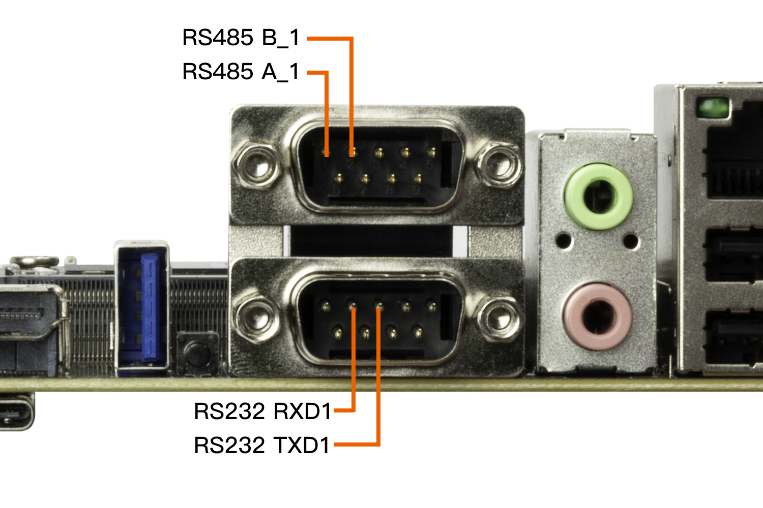
AIO-3588SJD4 supports RS232, RS485 interfaces
The serial interface diagram of the AIO-3588SJD4 development board is as follows:

12.2. DTS configuration
The RS232 interface of the development board is extended by the main control UART0, and the RS485 interface is extended by the main control UART3.
File path kernel-5.10/arch/arm64/boot/dts/rockchip/aio-3588sjd4.dtsi
&uart0 {
    status = "okay";
    pinctrl-names = "default";
    pinctrl-0 = <&uart0m2_xfer>;
};

&uart3 {
    status = "okay";
    pinctrl-names = "default";
    pinctrl-0 = <&uart3m2_xfer>;
};
After configuring the serial port, the nodes on the software corresponding to the hardware interface are:
RS232 :   /dev/ttyS0
RS485 :  /dev/ttyS3
12.3. Send and receive verification
Users can use different host’s USB-to-serial adapters to send and receive data to the serial port of the development board according to different interfaces. For example, the debugging steps of RS485 are as follows:
(1) Connect the hardware
USB to RS485 serial port cable
Host serial adapter (USB to 485 to serial module) connect to the host
(2) Development board sends, host receives
# The host terminal executes first:
# /dev/ttyUSB0 is the node of the host serial adapter, modify it according to the actual situation
cat /dev/ttyUSB0

# The development board debugs the serial port terminal and executes:
# /dev/ttyS3 is the RS485 node
echo "firefly RS485 test..." > /dev/ttyS3
The host terminal will receive the string “firefly RS485 test…”
(3) Host sends, development board receives
# To debug the serial terminal on the development board, execute first:
# /dev/ttyS1 is the RS485 node
busybox  stty -echo -F /dev/ttyS3     # turn off echo
cat /dev/ttyS3

# The host terminal executes:
# /dev/ttyUSB0 is the node of the host serial adapter, modify it according to the actual situation
echo "firefly RS485 test..." > /dev/ttyUSB0
The development board debugs the serial terminal to receive the string “firefly RS485 test…”
