13. UART
13.1. Hardware interface
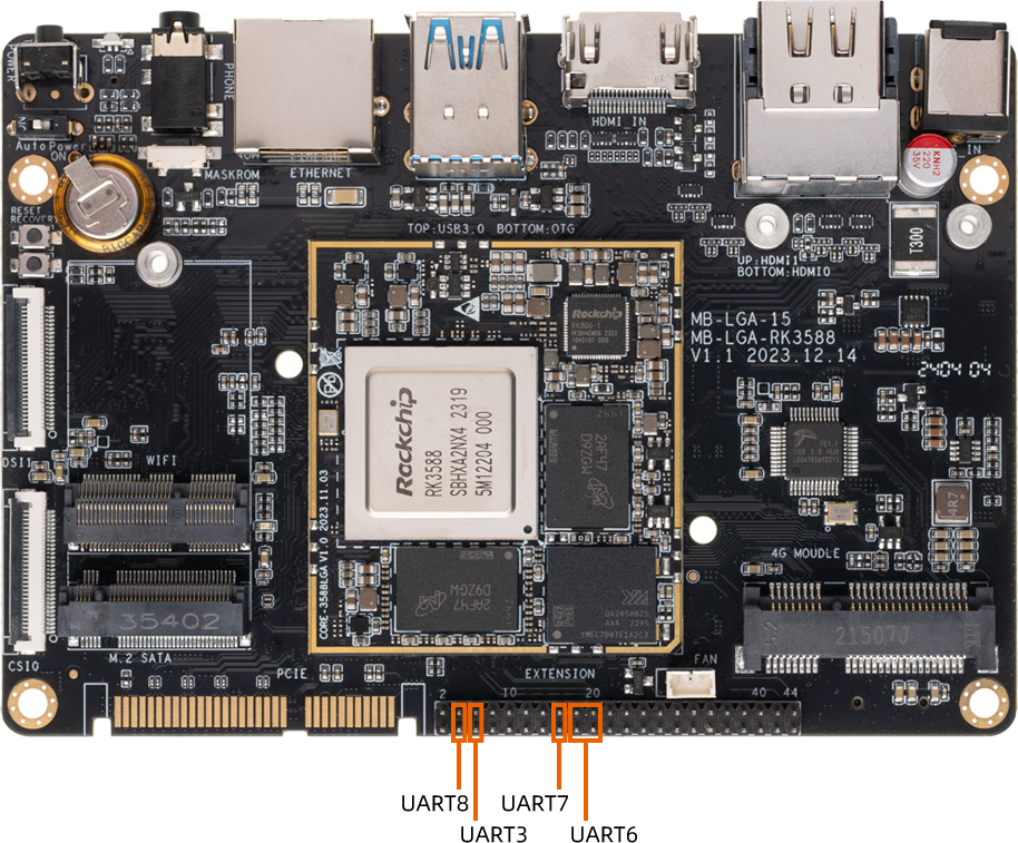
Core-3588L The following figure shows the serial port of the hardware version:

13.2. DTS config
File path kernel-5.10/arch/arm64/boot/dts/rockchip/aio-3588l.dtsi
There is one M.2 SATA interface on the development board AIO-3588L
#define CAN1_OR_UART3 0 /*1 = CAN1 , 0 = UART3 */
...
...
...
//ext gpio
&uart6 {
    pinctrl-names = "default";
    pinctrl-0 = <&uart6m1_xfer &uart6m1_ctsn &uart6m1_rtsn>;
    status = "okay";
};

&uart7 {
    pinctrl-names = "default";
    pinctrl-0 = <&uart7m1_xfer>;
    status = "okay";
};

&uart8 {
    pinctrl-names = "default";
    pinctrl-0 = <&uart8m1_xfer>;
    status = "okay";
};

#if CAN1_OR_UART3
&can1 {
    status = "okay";
    assigned-clocks = <&cru CLK_CAN1>;
    assigned-clock-rates = <200000000>;
    pinctrl-names = "default";
    pinctrl-0 = <&can1m0_pins>;
};
#else
&uart3 {
    pinctrl-names = "default";
    pinctrl-0 = <&uart3m1_xfer>;
    status = "okay";
};
#endif
After the serial port is configured, the node corresponding to the hardware interface
UART3:   /dev/ttyS3
UART6:   /dev/ttyS6
UART7:   /dev/ttyS7
UART8:   /dev/ttyS8
13.3. UART send and receive
The easiest way to do this is to stub the UART7 TX RX pin and then use the command to execute the command in the debug serial port or ADB
busybox  stty -echo -F /dev/ttyS7          # Close the echo
cat /dev/ttyS7 &                           # Get /dev/ttyS7
echo "firefly uart test..." > /dev/ttyS7   # Input string
The final debugging serial port terminal can receive the string “firefly uart test…”
