Firefly Cluster Server Product WIKI
Product introduction
1. product description
Firefly Cluster Server is a cluster server with high density ARM core board. The server is designed as rack unit size.The core board is based on Rockchip Soc platform. The cluster server has good adaptability in multiple fields such as cloud phone and edge computing. firefly cluster server has been iterated through several software and hardware versions, and now has perfect and reasonable software and hardware system support, and has the following features.
High density core.
The R1 version of the cluster server is 1U in size and supports the integration of 11 discrete core boards.
The R2 version of the cluster server is 2U in size and supports 72 integrated discrete boards.
Core board configurable
According to the requirements of the business scenario, the core boards of the cluster server can be selected in different specifications. And it also supports different specification boards mixed plugging. Such as cloud phone, AI computing, blockchain computing, etc., all can choose different specifications of core boards.
Core board software system independent
Each core board of the cluster server can run Android/Linux operating system independently. Failure of a single core board will not cause the entire server to go down.
BMC Visual Management System
The BMC management unit of the cluster server enables users to monitor, configure, and update the system of the core board in the web browser.
Hot-swappable design
The power supply unit, sub core board unit, network unit, temperature control unit, and expansion storage unit of the cluster server are all designed to be hot-swappable, which can effectively reduce the deployment and maintenance work of the server.
Redundant design
The power management unit and network management unit of the cluster server are designed with redundancy, which can cope with the sudden failure of some power supplies and networks.
Temperature control design
The integrated temperature control unit of the cluster server can effectively adjust the working status of the cooling fan by monitoring the ambient temperature and core temperature inside the server to optimize the overall performance and stability of the server.
2. product specifications
(1). Technical specifications
| Model | Cluster Server R1 | Cluster Server R2 |
|---|---|---|
| Number of core cards | 11 | 72 (hot-swappable design) |
| Architecture | ARM Architecture | ARM Architecture |
| OS | Support Android, Ubuntu, Linux OS | Support Android, Ubuntu, Linux OS |
| Network | 1GE Gigabit RJ45 network port 4 of which: the main core board network port 1, ordinary network port 3 | Dual NIC redundant design, single NIC integration: Gigabit network port (RJ45) × 2, 10 Gigabit network port (SFP +) × 2BMC network interface |
| 4G | 4G/LTE/5G network (optional) | Not supported |
| Display | 1×Mini HDMI 2.0, 4K@60Hz (motherboard display) | 1×Mini HDMI 2.0, 4K@60Hz (motherboard display) |
| Extended Storage | 3.5" STAT Hard Drive | 3.5" STAT Hard Drive / SD Card |
| USB | 2 × USB2.0 HOST1 Type-C | 1 × USB3.0 HOST |
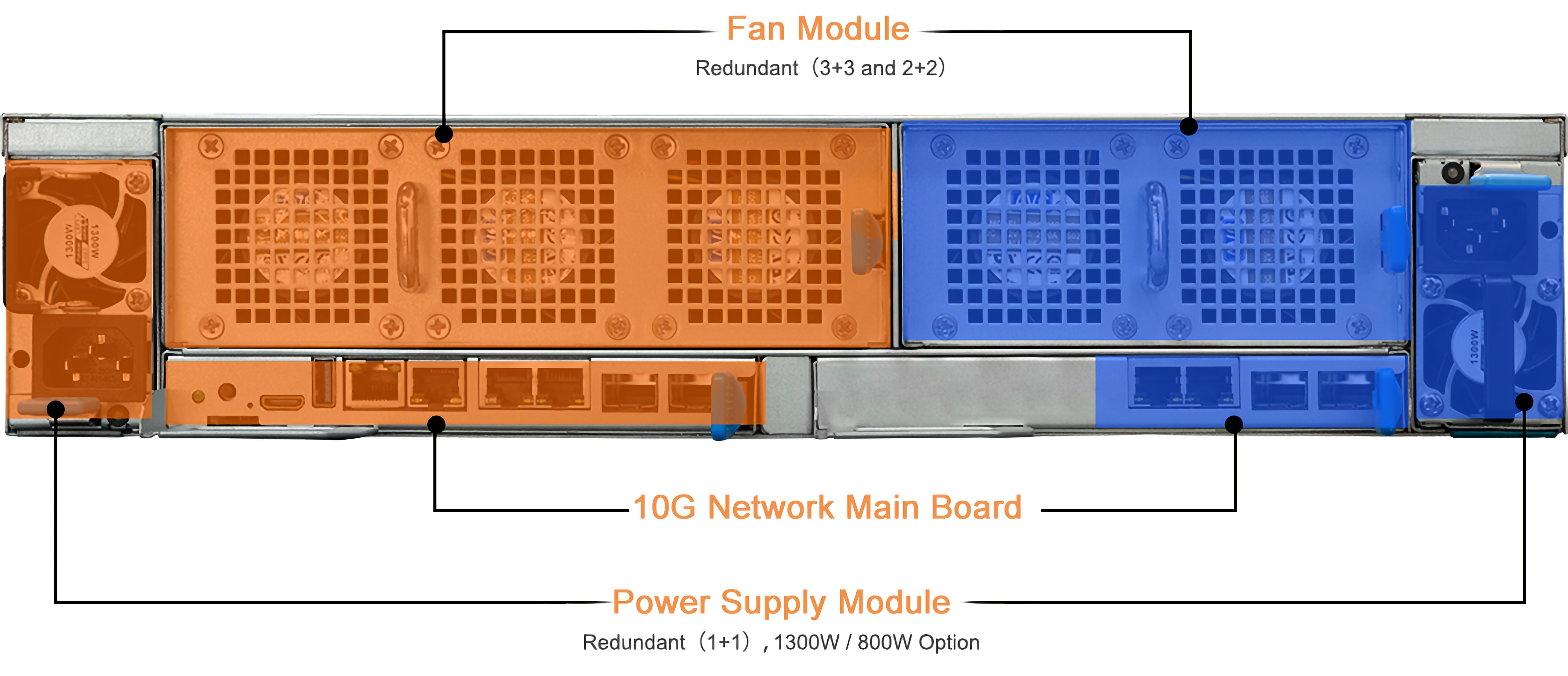
| Power supply | 300W AC power supply (input: 100V AC ~ 240V AC) | Dual redundant power supply design : AC 100~240V 50/60Hz, 1300W / 800W optional |
| Cooling | Heat sink + 5 high-speed cooling fans | Heat sink + 2 fan modules: Fan Module 1 (3×2 redundant fan design), Fan Module 2 (2×2 redundant fan design) |
| UID | None | UID button×1 |
| Hardware Watchdog | Yes | Yes |
(2). Sub-board specifications
| Model | Cluster Server R1 | Cluster Server R2 |
|---|---|---|
| Number of Nodes | All-in-One 1U Server | 9 Blade Nodes Each node can be configured with 8 processor core boards Node 9 can be used to install two 3.5" SATA/SSD hard drives |
| Number of Cores | Up to 11 Processor Core Boards | Up to 72 Processor Core Boards |
| Core Board | RK3399(AI) Core Board (Core-3399-JD4) RK3328 Core Board (Core-3328-JD4) RK1808(AI) Core Board (Core-1808-JD4) RK3588 Core Board (Core-3588SJD4) |
RK3399(AI) Core Board ( Core-3399-JD4) RK3328 Core Board (Core-3328-JD4) RK1808(AI) Core Board (Core-1808-JD4) RK3588 Core Board (Core-3588SJD4) |
| Internal Memory | 1GB / 2GB / 4GB | 1GB / 2GB / 4GB |
| Storage | eMMC 3.5-inch HDD 1 SATA/SSD HDD |
eMMC 3.5-inch SATA/SSD HDD bay x2 (node 9) SD card x1 |
Description: Firefly will continue to launch higher performance, larger memory core daughterboards, supporting 8 / 16G memory
(3). Physical specifications
| Model | Cluster Server R1 | Cluster Server R2 |
|---|---|---|
| Dimensions | Standard 1U Rackmount: 490mm x 390mm x 44.4mm | Standard 2U Server Chassis: 580mm x 434mm x 88.8mm |
| Weight | Server mainframe: 5.8 kg Total package weight: 7.2 kg | Total package weight: 29 kg |
(4). Environmental specifications
| Model | Cluster Server R1 | Cluster Server R2 |
|---|---|---|
| Operating Temperature | 0ºC - 40ºC | 0ºC - 50ºC |
| Operating Humidity | 8%RH~95%RH | 10%RH~80%RH |
Instructions for use
1. Whole machine description
(1). Physical map
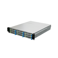
Cluster Server R2 (9 knives)
“The old cluster server Cluster Server R2 (6 knives no maintenance) physical map”
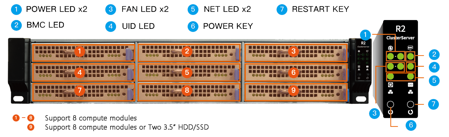
(2). Button description
1. POWER LED x2 Power status indicators: correspond to the two power supplies on the left and right of the host (front view). The power supply is normal and the LED in the corresponding position is red.
2. BMC LED Motherboard status indicator: it lights up when the main motherboard of the host enters the system normally.
3. FAN LED x2 Fan status indicator: the fan is normally green, the fan speed is abnormal or the fan module is not connected, the LED at the corresponding position is red, and a buzzer sounds.
4. UID LED UID indicator: Press the UID button (the 10th button on the back), which is always on, which is convenient for maintenance personnel in the computer room.
5. NET LED x2 The switch status indicator, which is normally green, and the LED in the corresponding position is red if the switch is abnormal or not connected.
6. POWER KEY Power button: Press the button without releasing it, and you will hear the buzzer prompt, and release the button immediately after the prompt disappears (the duration is 3s). For details, please check the switch operation.
7. RESTART KEY Reset button: Press the reset button to force the main board to restart.
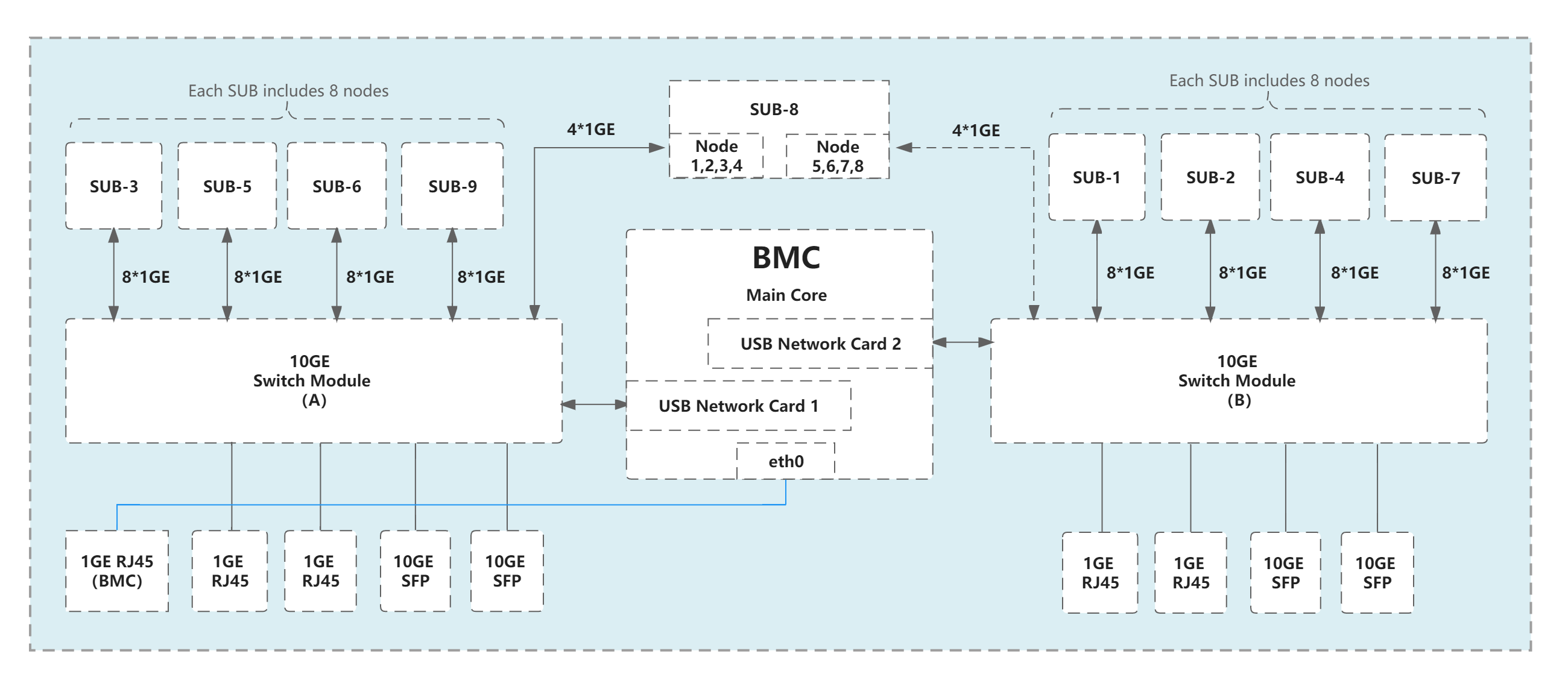
(3). Network topology diagram
(4). Switch on and off
Normal startup: When the host is off, press the
POWER KEYwithout releasing it for a few seconds.Normal shutdown: When the host is turned on, press the
POWER KEYwithout releasing it, and hear the buzzer prompt for 3s. After the host confirms the shutdown state, the buzzer prompt disappears, immediately release the button. The host performs a normal shutdown.Forced shutdown (generally not recommended): When the host is turned on, press the
POWER KEYwithout releasing it, and hear the buzzer sound for 5s, the host is forced to power off.
The condition for achieving normal shutdown is the linux system installed on the main core and firefly-sr-service-*.deb is installed, and the factory firmware has been installed by default.
2. BMC Management System
The BMC management system is a software system running on the BMC management unit of the cluster server, which is a control board (hereinafter referred to as the main board) using RK3399 as the main controller chip. The motherboard runs Ubuntu 18.04 system and interacts with other core boards (hereinafter referred to as daughter boards) in the cluster server through network and USB interfaces to monitor and manage each core board of the cluster server. Its software stack is composed of.
node_exporter: Runs on the motherboard and daughterboards and is responsible for collecting monitoring data from the device.
Prometheus: runs on the motherboard and is responsible for collecting and storing monitoring data from each device.
Grafana: runs on the motherboard and is responsible for monitoring the centralized display of charts.
The advantage of this solution is that the motherboard deploys the node_exporter to each device (the OS of the daughter board can be Android or Ubuntu) and displays the resource usage of each daughter board in a visual graph.
(1). Login
External HDMI display.
Connect the HDMI display, USB mouse and keyboard to the cluster server, and you will have access to the graphical Ubuntu system in the BMC management unit. Launch the browser and enter http://127.0.0.1:3000 in the address bar to open the BMC system.
Remote login to the BMC system.
To access through an external browser, you first need to ensure that the host on the access end is on the same LAN as the BMC, and then obtain the BMC management system IP address through the BMC scan tool. You can also obtain the BMC management system IP address by connecting to the cluster server HDMI monitor and logging into the BMC management unit Ubuntu system. Then enter http://ipaddr:3000 in the browser address to access the BMC system.
Using the BMC scan tool.
BMC Scan Tool can get all the BMC management system IP addresses in the same LAN, it will scan the LAN once by default after opening the tool, or you can scan manually by refreshing the button  to scan manually, according to the list of BMC management system IP addresses presented in the software interface, click the corresponding
  icon to open an external browser and enter the BMC management system login page for the corresponding IP address.
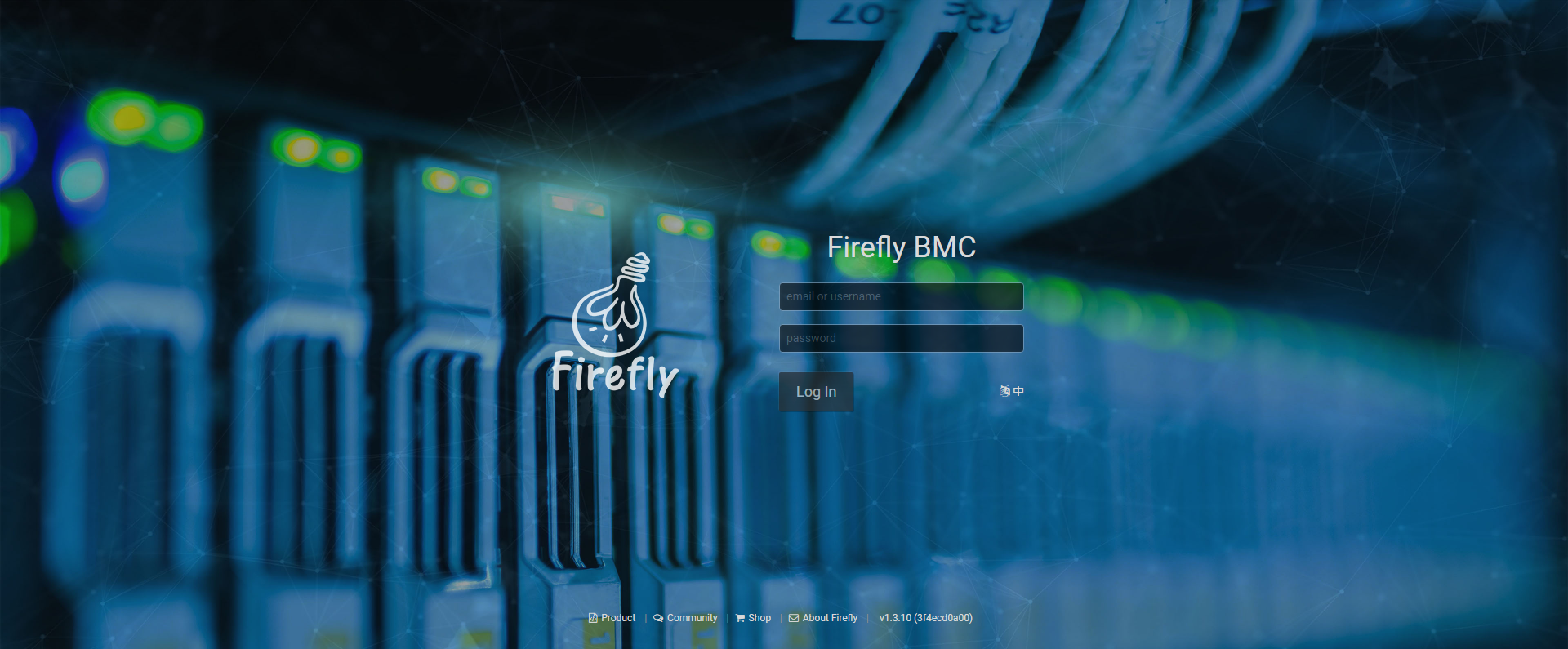
Enter the initial login “admin” and password “admin”, and click the Login button to enter the device list page.
(2). Device list
You will be taken to the device list page by default after login. Any time you need to access the device list page, click on the  icon on the left toolbar to access.
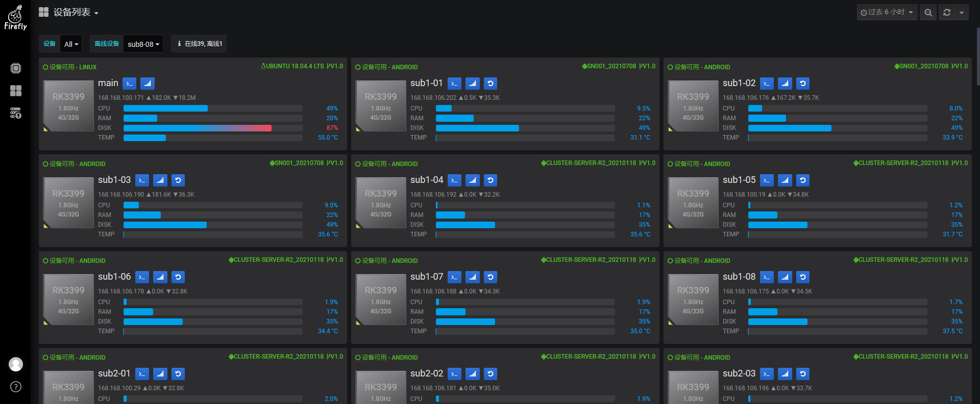
This is a list of all devices in the cluster server, each card represents one device.
In the upper left corner of the device list page, there are two drop-down lists.
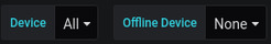
(1). Devices: You can filter the devices that need to be displayed, which is useful in case of more devices.
(2). Offline Devices: For quick view of the list of offline devices only.
Looking down, this is a diagram of the peripheral interfaces provided by the server (only R1 has this panel): 4 network ports, dual-layer USB, HDMI, OTG, Sim Card, disk.
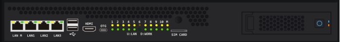
U: LAN Indicates: the on/off of the yellow LED above corresponds to the network status of the device.
D: WORK means: the green LED below is on/off corresponding to the operating status of the device.
The device card will display differently according to the device state:
The device is accessable to the the motherboard via adb, and has entered a normal OS:

At the top of the card, the “NORMAL” status is displayed in green on the left followed by the current OS. Versions of OS and hardware (only R2 has hardware) are shown of the right.
The icons on the left indicate the CPU model (number of CPU cores and maximum frequency), DDR memory (4G) and eMMC capacity (32G) of the core board.
“sub04”: indicates the numbering of the device.
 : click on this button to go to the Shell terminal window.
 : click on this button to enter the resource detail page for this device.
 : click this button to reset the device’s power.
The second line on the right of the card shows the IP address and connection rate of the device’s primary network interface, and all network interface addresses and rates are displayed on mouse hover (currently only the motherboard has multiple network interfaces).
The four box plots show CPU, memory, and disk usage, as well as the CPU temperature.
The device is offline, i.e. when the USB communication with the motherboard fails due to physical removal of the device, firmware failure, or OS exceptions:
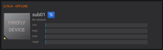
The status “OFFLINE” is displayed in orange at the top of the card.
 : Click this button to reset the device’s power.
The device is in maintenance, i.e. the device might be in loader, netrecovery(a auxiliary os to flash firmware from http server), android_recovery or android_offline:
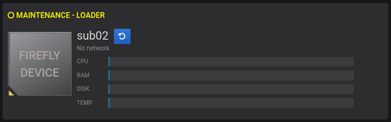
The status “MAINTENANCE” followed by detailed state will be shown in yellow at the top of the card.
There is no monitoring display due to mantenance mode.
- : Click this button to reset the device’s power.
(3). Dashboard list
In the device list or other dashboard pages, click on the dashboard name in the upper leftmost corner at

Additional dashboards can be viewed at
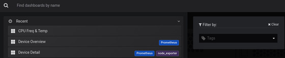
The following dashboards are currently available:
Device overview
Device details
CPU frequency and temperature monitoring
In the dashboard page, the toolbar in the upper right corner allows you to select the viewing period and how often it will be updated automatically. The image below shows the last 6 hours of data, and updates every 5 seconds.
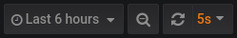
Click the  button to manually refresh the monitoring data page display.
A. Equipment Overview
The dashboard list, or by clicking on the  icon on the left toolbar to access the device overview page at
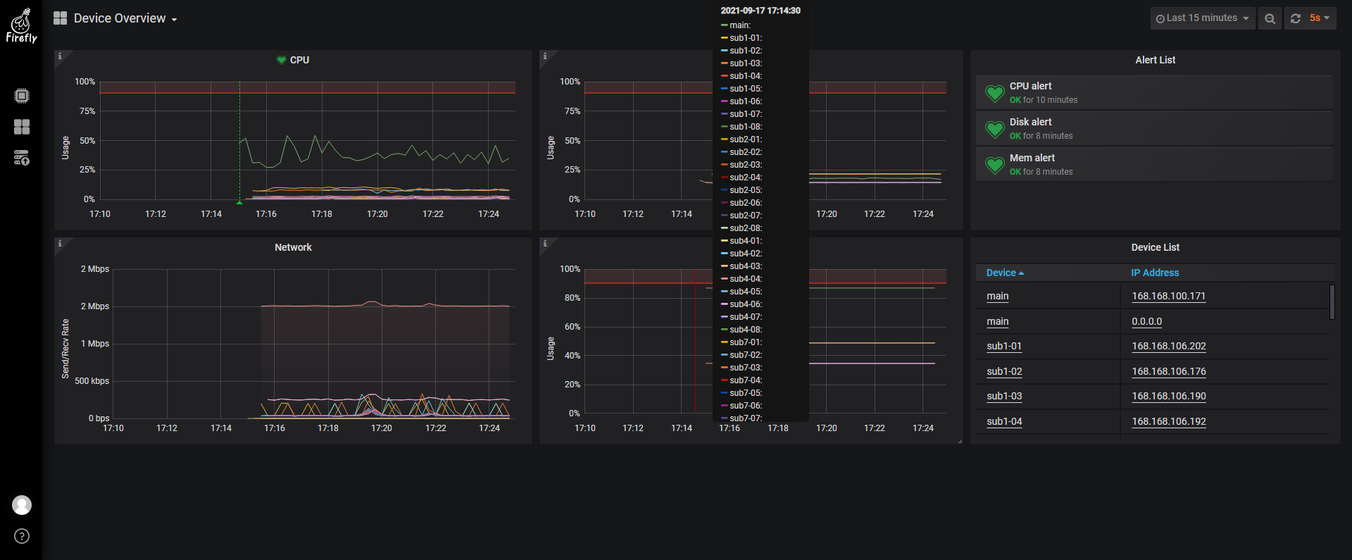
The Device Overview page displays the CPU, memory, disk and network data of all devices in one place:
Mouse hover over the graph to display the detailed values of the devices.
The “Alarm list” on the top right, when CPU, memory and disk exceed the red alarm line for a period of time, an alarm action is triggered, such as sending an email (this function requires configuration of relevant parameters, to be explained).
The “Device List” at the bottom right lists the node names and IP addresses of all online devices for easy viewing. Mouse click to view the device details page of the device.
B. Equipment Breakdown
There are several ways to access the device details page:
on the device list page by clicking on the
 button on the device list page;
Click on the table item on the device list on the right in the device overview page;
Access through the dashboard list.
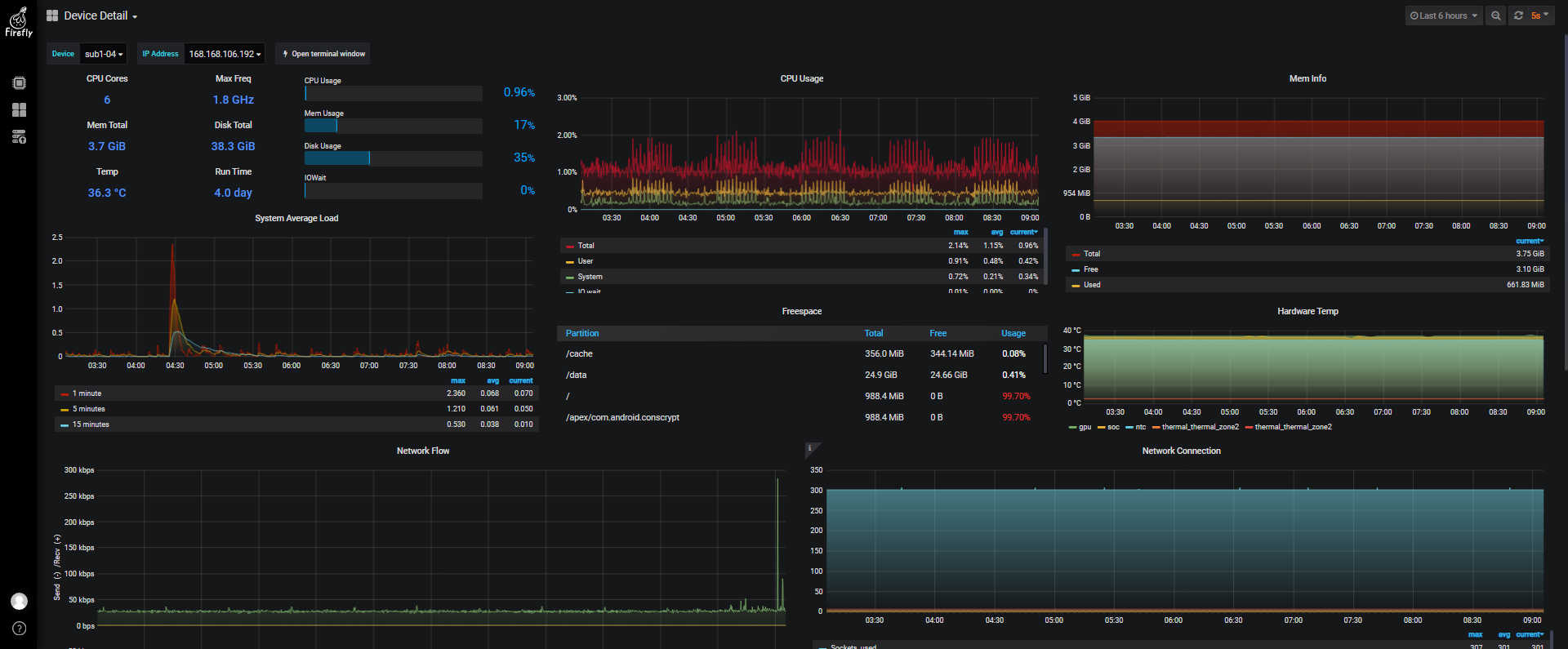
The Device Detail page, which provides detailed monitoring data of resources, allows users to select one of the devices to view its detailed resource usage.
The node drop-down selection box on the top left switches the detailed display of the device, and the IP address is the IP address of all network interfaces of the device (for information display purposes only).

The quick toolbar on the right, click on to open the Shell Terminal window for that device.

Use the scroll bar on the right to scroll down to see more monitoring items.

C. CPU Frequency and Temperature Monitoring
The CPU frequency and temperature monitoring page is used to compare CPU frequency with SOC and GPU temperature during the development phase to see if the temperature will continue to rise due to insufficient fan cooling performance, which will lead to forced CPU downscaling.
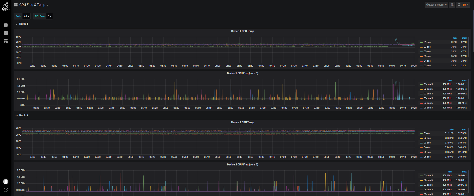
The RK3399 has 6 CPU cores, small cores 0~3, large cores 4~5. Generally, you can observe the large cores, because of the page space, only one core is displayed at the same time. The core display can be switched by the upper drop-down bar.

(4). Shell terminal window
There are several ways to access the Shell terminal window of a device: 1. Click on the device list page and click on the  button on the Device List page; 2. Click on the Quick Toolbar in the upper right corner of the Device Details page
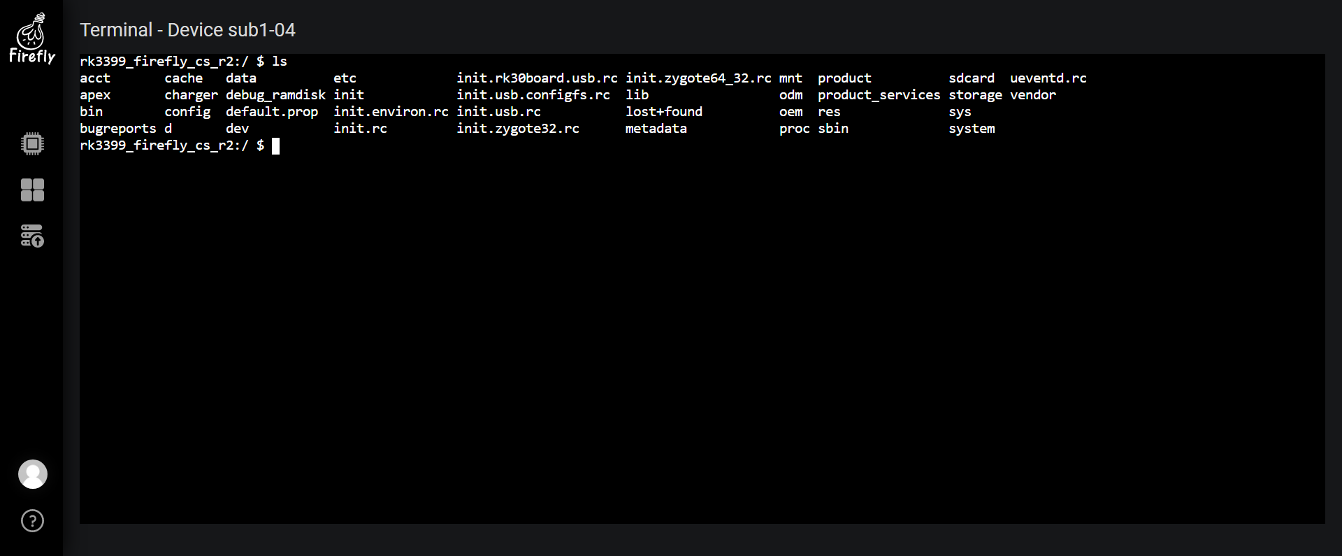
The motherboard’s Shell terminal window is the root shell under the motherboard’s Ubuntu system and has superuser privileges, allowing it to execute various system maintenance commands and operate each daughter board via adb.
The shell terminal window for the daughterboard is the adb shell, and you can run the su command to switch to the root user.
To facilitate management, Firefly cluster monitoring system introduces command line management tool bmc, which can quickly perform a variety of daily sub-board operations and batch operations. Please see chapter bmc - Specific command line tool for details.
(5). Daughter board firmware upgrade
Preparation:
IMPORTANT: All devices demand valid IP addresses from DHCP server. Do keep cluster server connected to a valid router.
The OTG USB port of the cluster server MUST NOT be connected with the PC.
The filename of the firmware needs to has a suffix of “.img” as extension, and be placed in the
/home/firefly/Firmwaredirectory of the motherboard.
Click on the  icon on the left toolbar to access the daughter board firmware upgrade page at
Click the button in the upper right corner  to go to the “Add new daughter board firmware upgrade” page.
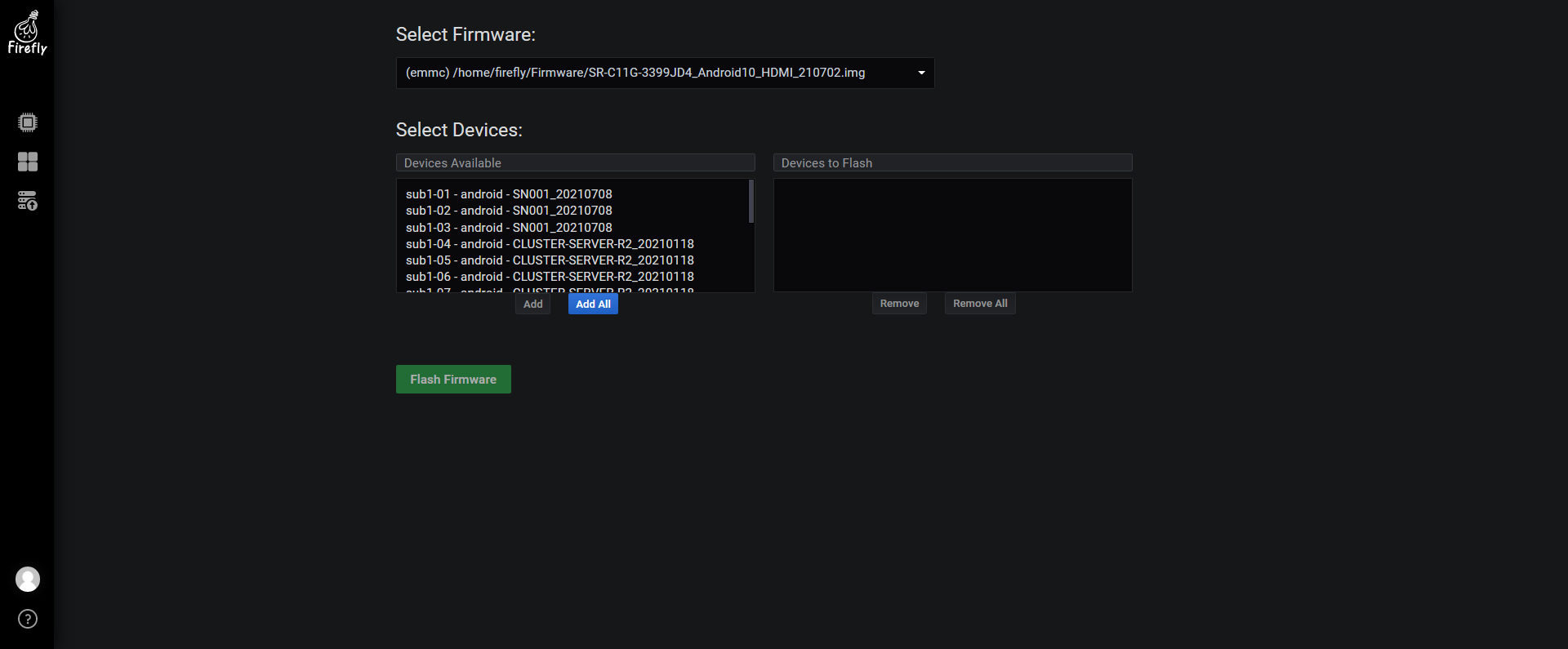
Just select Upgrade Firmware and choose from the drop-down list.
Select upgrade device: On the left is the list of available devices, and on the right is the list of devices to be upgraded.
To upgrade all devices, press the “Add All” button to add all available devices to the list on the right.
To upgrade one or two devices, double-click directly on the corresponding device to add the individual device to the list on the right.
The edit box above the device list is for filtering purposes, so you can quickly filter out the desired devices.
Press the “Delete All” button to clear the list of devices to be upgraded.
Ctrl+mouse click adds or removes a selection of individual devices; Shift+mouse click adds or removes a selection of consecutive devices. This is the same as the list selection operation on Windows. After selecting a device, press the corresponding “Add” or “Remove” button to add or remove the device to the list of devices to be upgraded.
Press the “Upgrade Firmware” button to start the firmware upgrade.
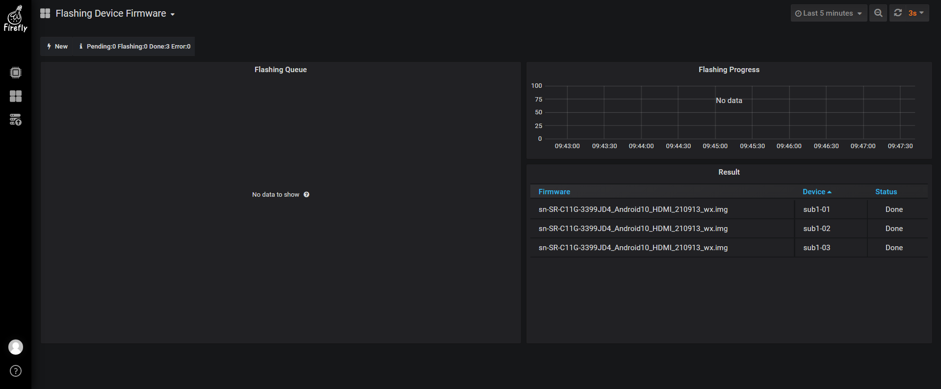
The page just submitted looks like this.
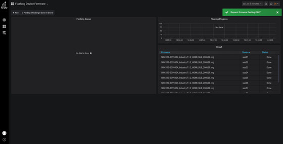
The firmware upgrade time is long (involves a series of background switching and read/write operations), please be patient. The background is refreshed every 15 seconds and the interface will show the following progress page.
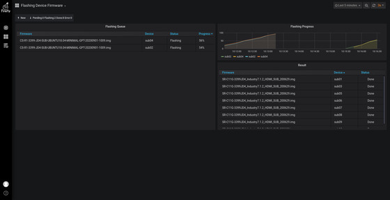
On the left is a list of upgraded devices and progress.
On the top right is the upgrade progress removal chart.
The bottom right is the list of completed devices (both successful and error-prone).
(6). Change password
Mouse over the user avatar in the lower left corner and select “Change Password” in the pop-up menu.
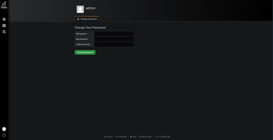
Enter the old password, the new password and confirm the new password, and finally press the “Change Password” button.
3. Other instructions for use
(1). Restore factory settings
Enter the following command in the terminal:
sudo recovery reset
The system enters the recovery mode to restore the factory settings, and it will automatically restart into the system after about 30s.
(2). System Recovery Method
If the Cluster Server R2 system is severely damaged and cannot be used normally, there are two methods:
(2.1). Use SD card to make upgrade card reinstall system
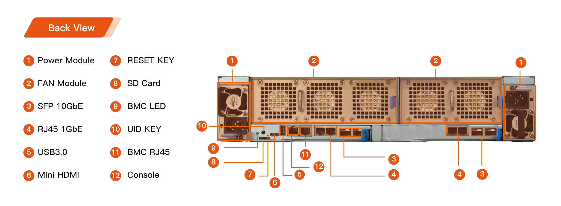
Cluster Server R2 reserved SD card interface (label 7 in the back view) can be used to read and write the SD card, and can also be used to flash the system in an emergency.
Insert the SD card into the SD card slot (label 7 in the back view)
Restart or press the reset button when the host is powered on, enter the main core startup and enter the programming mode
Pull out the SD card immediately after the programming is completed, and the system automatically restarts (the first startup after the upgrade is slightly slower, about 30s longer than the normal startup).
You can choose one of the following methods to confirm whether to enter the programming mode:
Through the fan module (back view note 2), you can see that the main core position inside the host will have a yellow light flashing
Console (back view label 12) connected to the serial port (baud rate 115200) will print the programming information
When connected to Mini HDMI, the programming information will be displayed
You can choose one of the following methods to confirm whether the programming is complete:
Through the fan module (back view memo 2), you can see that the main core position inside the host will have a yellow light that stops flashing and is always on
Console (label 12 in the back view) is connected to the serial port (the baud rate is 115200) and immediately pull out the SD card after seeing the prompt message
Please remove SD CARD!!!, wait for reboot..When the Mini HDMI is connected, the programming information will be displayed. After seeing the prompt message
Please remove SD CARD!!!, wait for reboot., pull out the SD card immediately.
(2.2). Upgrade via another server (need to be disassembled and not recommended)
Remove the core board of the main core, use the core board as a daughter board of another Cluster Server R2, and upgrade the corresponding motherboard firmware program through the BMC software
Power off the host
Press the blue buckle, pull out the main core board drawer (the bottom drawer just below the fan module in the back view label 2), and take out the main core board
Put the core board in the daughter board drawer of another Cluster Server R2, and enter the BMC software service for system programming
After the upgrade is complete, re-install back to the main core position of the main core board drawer (back view label 2 directly below the bottom drawer of the fan module), and insert the drawer (note that it must be fully inserted or it will not be able to boot)
Connect the power supply and start the system normally.
(3). How to deal with the loss of ADB on the daughter board
There are generally three situations in which the ADB connection of the daughter board is lost:
USB communication link is abnormal
The ADB service of the daughter board is abnormal
The daughter board system crashed
Conventional processing method:
Reset the power supply of the USB HUB where the daughter board is located. If recovery is invalid, perform 2 operation (may cause more daughter board ADB loss, it is recommended to perform operation 2)
Use the BMC management system to reset the power of the daughter board, and if the recovery is invalid, perform 3 operations
Use the BMC management system to reinstall the system on the daughter board
(4). openstf
BMC firmware has installed openstf, but openstf is closed by default due to resource occupation problems. If you want to open the service, you can enter the following command:
sudo systemctl start openstf
Note: Android 10 currently does not support openstf
Application scenarios
1. cloud phone
Each core board of Firefly Cluster Server can run an Android system independently. Users can deploy their mobile applications to each core board. For cloud phone application scenarios, Firefly Cluster Server adds the following features.
(1). Virtual hardware devices
Includes virtual camera, virtual sound card, etc. For professional technical support and more detailed information, please contact Business.
Virtual Camera
Smart devices that do not have a camera installed or cannot install a camera will result in applications that require the camera to be turned on not working; and Firefly’s virtual camera technology case can virtualize multiple cameras on the Firefly cluster server, through the virtual camera, users can load in the prepared video files/pictures, etc. and let these virtual cameras output these image information .
Virtual Sound Card
It is well known that playing audio and video files on a device without a sound card will result in “No audio device found…” “There is a problem with the device due to sound…” And so on prompt and can not play. Firefly’s virtual sound card technology cases can be virtualized on the Firefly cluster server sound card, you can play audio files without a sound card device, and will not be unable to play because of the prompt no equipment.
(2). NFS, iSCSI network storage
Firefly cluster servers (including android, linux systems) provide NFS, iSCSI network storage solutions to achieve unified management of storage resources. Professional technical support and more detailed information, please contact business.
NFS
NFS (Network File System) is useful for sharing directories and files among multiple users on the same network. By using NFS, users and programs can access files on remote systems as if they were local files.
iSCSI
iSCSI ( Internet Small Computer System Interface). iSCSI uses the TCP/IP protocol (generally using TCP ports 860 and 3260) to exchange SCSI commands between two computers using the iSCSI protocol. commands, so that the computer can be high-speed LAN hub to SAN (Storage Area Network) emulation as a local storage device. It can be used to connect server computers (e.g., database servers) to storage arrays on disk volumes. It has better read/write efficiency and stability than NFS.
(3). Virtual Android system
Virtual Android system is to virtualize multiple Android systems in one Soc by using container and virtual device technology, and each Android system runs independently of each other. For users, if a sub-core board virtualizes three Android devices, a cluster server can virtualize up to 216 Android devices. Virtual Android systems have a wide range of applications in neighborhoods such as application testing and social media operations.
2. cloud computing
The Firefly cluster server has various configurations of sub-core boards (see ). Among them, RK3399 adopts dual-core A72+4-core A53 architecture with integrated MaliT860P4 GPU, while RK1126 adopts RK’s latest generation NPU architecture with AI arithmetic power up to 3T. so it is also appropriate to use Firefly Cluster Server as a cloud computing platform. For the cloud computing platform, Firefly cluster server enhances the following features support.
(1). Ubuntu Minimal system support
The Ubuntu system is very easy to set up, deploy and update in the working environment, etc. The Ubuntu Minimal system on the Firefly cluster server sub-core board has the following advantages.
No desktop environment and a low resource footprint, requiring only 40M of memory after simplified network management.
Streamline system services for embedded platforms.
Provides Rockchip VPU + Mpp based video hard codec support.
Provides OpenGL, OpenCL support based on Arm Mali GPU.
Adapted to QT, Docker, Electron and other development frameworks .
Provides a range of interfaces to operate on-board resource devices.
System uses overlayfs file system, supports exporting rootfs, secondary packing, restoring factory settings, etc.
(2). Multiplex IPC decoding + AI inference
Firefly Cluster Server, the core board with the solution using RK3399 + RK1808 x N, realizes the decoding and AI analysis of multiple network video streams. In this solution, the cluster server connects multiple webcams for video data collection, and uses the powerful video decoding function of RK3399 to decode the collected video streams and distribute them to AI acceleration chip RK1808 to complete AI analysis; then collects the results of AI analysis and outputs them to the user side in real time.
For details, see: Multiplex Video Decoding and AI Analysis
BMC secondary development
1. Monitoring data acquisition
All monitoring data is stored in the Prometheus database on the motherboard and can be retrieved using its command tool promtool.
Monitoring data is fetched through node_exporter.
The web dashboard definition json file is stored in /var/lib/grafana/dashboards/.
(1). Get the instant online status of all subboards
$ promtool query instant http://127.0.0.1:9090 node_cluster_up
node_cluster_up{instance="127.0.0.1:9100", job="node", nodename="main", state="android",  subnode="sub1-01"} => 1 @[1608772515.659]
node_cluster_up{instance="127.0.0.1:9100", job="node", nodename="main", state="android",  subnode="sub1-02"} => 1 @[1608772515.659]
node_cluster_up{instance="127.0.0.1:9100", job="node", nodename="main", state="android",  subnode="sub1-03"} => 1 @[1608772515.659]
node_cluster_up{instance="127.0.0.1:9100", job="node", nodename="main", state="android",  subnode="sub1-04"} => 1 @[1608772515.659]
...
subnode: subboard number
state: the state of the daughter board
android: The operating system that the daughter board runs on is Android.
linux: The daughter board runs Linux as the operating system.
netrecovery: The daughterboard is in the auxiliary upgrade system netrecovery state.
offline: The daughter board is offline and cannot be detected via USB connection.
online: The daughter board can be detected via USB connection, but no further status can be resolved.
loader: The daughter board is in the Loader state.
fastboot: The daughter board is in the Fastboot state.
adb: The daughterboard is recognized as an adb device, but its operating system is not recognized yet.
adb_offline: The daughterboard is recognized as an adb device in the offline state and cannot perform normal adb operations.
android_recovery: The daughterboard has entered the Android recovery system.
metric:
1.0: The daughterboard is in android or linux state.
0.0: The daughter board is in offline state.
0.5: The daughter board is outside all the states above.
(2). Get the host temperature
A. Get motherboard temperature (R2 only)
Get temperature in Celsius measured from the thermistor on motherboard:
$ promtool query instant http://127.0.0.1:9090 'node_hwmon_temp_celsius{chip=~"platform_ntc.*"}'
node_hwmon_temp_celsius{chip="platform_ntc", instance="127.0.0.1:60101", job="node", nodename=" sub1-01", sensor="temp1"} => 34.779 @[1608773513.849]
node_hwmon_temp_celsius{chip="platform_ntc", instance="127.0.0.1:60102", job="node", nodename=" sub1-02", sensor="temp1"} => 42.81 @[1608773513.849]
node_hwmon_temp_celsius{chip="platform_ntc", instance="127.0.0.1:60103", job="node", nodename=" sub1-03", sensor="temp1"} => 43.305 @[1608773513.849]
...
B. Obtain the ambient temperature inside the host (R2 only)
The ambient temperature (in degrees Celsius) inside the host computer is obtained by reading the data from the ds18b20 temperature sensor inside the host computer.
$ promtool query instant http://127.0.0.1:9090 'node_cluster_env_temp_celsius'
(3). Get the speed of the fan (R2 only)
Unit: RPM (revolutions per minute)
$ promtool query instant http://127.0.0.1:9090 node_cluster_fan_speed
node_cluster_fan_speed{fan="fan1", instance="127.0.0.1:9100", job="node", nodename="main"} => 7812 @[1607501007.839]
node_cluster_fan_speed{fan="fan2", instance="127.0.0.1:9100", job="node", nodename="main"} => 7936 @[1607501007.839]
...
R2v2 has 10 fans with adjustable speed.
(4). Get the harddisk info
Get the device name and model:
$ promtool query instant http://127.0.0.1:9090 node_cluster_disk_up
node_cluster_disk_up{device="sda", instance="127.0.0.1:9100", job="node", model="ST1000DM010-2EP1", nodename="main"} => 1 @[1609228221.442]
Get total capacity in bytes:
$ promtool query instant http://127.0.0.1:9090 node_cluster_disk_bytes_total
node_cluster_disk_bytes_total{device="sda", instance="127.0.0.1:9100", job="node", nodename="main"} => 1000204886016 @[1609228289.651]
Get space available in bytes:
$ promtool query instant http://127.0.0.1:9090 node_cluster_disk_bytes__used
node_cluster_disk_bytes_used{device="sda", instance="127.0.0.1:9100", job="node", nodename="main"} => 121475072 @[1609228366.843]
(5). Get IP addresses of the devices
$ promtool query instant http://127.0.0.1:9090 node_network_ipaddr
node_network_ipaddr{device="eth0", instance="127.0.0.1:60101", ipaddr="168.168.101.198", job="node", nodename="sub1-01"} => 1 @[1609396443.993]
node_network_ipaddr{device="eth0", instance="127.0.0.1:60102", ipaddr="168.168.100.180", job="node", nodename="sub1-02"} => 1 @[1609396443.993]
node_network_ipaddr{device="eth0", instance="127.0.0.1:60103", ipaddr="168.168.101.145", job="node", nodename="sub1-03"} => 1 @[1609396443.993]
...
device: Network interface. Each daughterboard has only one (eth0) while the motherboard has multiple.
ipaddr:IP address. If not available, “0.0.0.0” is displayed.
nodename:device node name(subXX for daughterboard, and main for motherboard).
2. Hardware control
(1). Reset power of the daughter board
Function: Reset power of the daughter board
Description: Reset the power of the daughter board by manipulating the RESET pin of the daughter board for the purpose of forcibly restarting the daughter board. If the daughter board does not have a RESET pin, it can be powered off and on.
Calling :
Command line: /usr/bin/bmc
reset Web API: GET http://localhost:7070/api/reset/
(2). Reboot OS of the daughter board
Function: Reboot OS of the daughter board
Description: First reboot the system by adb reboot command, if there is no response within 10 seconds, then force reboot the daughterboard by resetting the power.
Calling :
Command line: /usr/bin/bmc
reboot Web API: GET http://localhost:7070/api/reboot/
(3). Power on the daughter board (R2 only)
Function: Turn on the power of the daughter board
Description: Power on the daughter boards by manipulating their POWER pins. All daughter boards are powered on by default when the cluster server is powered on.
Calling :
Command line: /usr/bin/bmc
poweron Web API: GET http://localhost:7070/api/poweron/
(4). Power off the daughter board (R2 only)
Function: Power off the daughter board
Description: Power off the daughter board by manipulating the POWER pin of the daughter board.
Calling :
Command line: /usr/bin/bmc
poweroff Web API: GET http://localhost:7070/api/poweroff/
3. firmware upgrade
Use the script to add a firmware upgrade task.
sudo netrecovery-master queue <absolute path to firmware file> <device name> [<device name> ...]
For example.
sudo netrecovery-master queue /home/firefly/Firmware/xxx.img sub1-01 sub1-02
Check the progress of the firmware upgrade at
$ promtool query instant http://127.0.0.1:9090 node_cluster_firmware_upgrade_stat
node_cluster_firmware_upgrade_stat{firmware="SR-C11G-3399JD4_Android10_HDMI_201202.img", instance="127.0.0.1:9100", job="node", node="sub02", nodename="main", state="done"} => 100 @[1608795873.055]
node_cluster_firmware_upgrade_stat{firmware="SR-C11G-3399JD4_Android10_HDMI_201202.img", instance="127.0.0.1:9100", job="node", node="sub03", nodename="main", state="done"} => 100 @[1608795873.055]
node: The daughter board number of the upgraded firmware.
state: preparing: being prepared; flashing: being burned; done: completed; error: error.
metric: percentage of burn progress, e.g. 100 means all completed (100%).
Note: There may be two different states for the same daughter board, if there is state=”flashing” then the daughter board is still in the process of burning, so it is safer to check the flashing progress first, if there is, then it is in the process of upgrading, if not, then check whether it is completed or there is an error.
$ promtool query instant http://127.0.0.1:9090 'node_cluster_firmware_upgrade_stat{node="sub02",state="flashing"}'
$ promtool query instant http://127.0.0.1:9090 'node_cluster_firmware_upgrade_stat{node="sub02",state=~"done|error& quot;}'
node_cluster_firmware_upgrade_stat{firmware="SR-C11G-3399JD4_Android10_HDMI_201202.img", instance="127.0.0.1:9100", job="node", node="sub02", nodename="main", state="done"} => 100 @[1608796078.37]
4. Up/download file, run command
The following commands use bmc_adb, which is a wrapper around the adb command, allowing the user to easily use the device name to operate the corresponding daughter board, regardless of adb serial number. Of course, the adb command can also be used if you know the adb serial number.
(1). Upload files from motherboard to daughter board
Run on the motherboard:
$ bmc_adb -s sub01 push home.json /data/local/tmp
(2). Download file from daughter board to motherboard
Run on the motherboard:
$ bmc_adb -s sub01 pull home.json /data/local/tmp
(3). Run command on the daughter board
Running on the motherboard.
$ bmc_adb -s sub01 shell ifconfig
5. bmc - the specific command line tool
The bmc command line tool must be run from a shell terminal window on the motherboard (i.e., the device with the node name main), although it can be used remotely by connecting to the motherboard via ssh.
Get help with the command.
$ bmc --help
Usage:

 bmc list [--offline] [<pattern>]
     List all the active nodes usable with adb, optionally matched by pattern

 bmc serials
     List all the active nodes with coresponding adb serial.

 bmc <node> {reset|poweron|poweroff}
     Invoke reset, poweron or power off on <node>

 bmc <node> state
     Show node state

 bmc <node> shell [<command>...]
     Invoke shell with command.

 bmc forall <command> %{node}
(1). List adb devices
List all online adb devices:
$ bmc list
sub03
sub04
sub05
sub06
sub07
sub08
sub09
sub10
List all devices with an adb status of offline:
$ bmc list --offline
(2). List device name and corresponding adb serial number
$ bmc serials
sub02 B09CCSUB02 usb:2-1.2.3
sub03 A8232SUB03 usb:2-1.2.4
sub06 4DE1ESUB06 usb:2-1.2.7
sub07 505C3SUB07 usb:2-1.1.2
sub08 FFBCCSUB08 usb:2-1.4
sub09 710AFSUB09 usb:2-1.1.1
(3). Reset power of the daughter board
$ bmc sub03 reset
 okay
(4). Power on/off the daughter board (Only R2)
Power off the device:
$ bmc sub1-01 poweroff
   okay
Power on the device:
$ bmc sub1-01 poweron
   okay
(5). Inspect daughter board status
Check device state in detail:
# One board
$ bmc sub1-01 state
android

# All boards
$ bmc state
main: linux
sub1-01: android
sub1-02: android
...

# All boards with offline state
$ bmc state | grep offline
sub7-01: offline
sub7-02: offline
sub7-03: offline
...
Show adb state and ifconfig result of sub3-01:
$ bmc sub3-01
node: sub3-01
state: android
adb_state: device
ifconfig:
eth0      Link encap:Ethernet  HWaddr ae:bb:8b:e7:b4:38  Driver rk_gmac-dwmac
          inet addr:168.168.100.171  Bcast:168.168.255.255  Mask:255.255.0.0
          inet6 addr: fe80::7298:5297:6ab9:7fd0/64 Scope: Link
          UP BROADCAST RUNNING MULTICAST  MTU:1500  Metric:1
          RX packets:66181 errors:0 dropped:0 overruns:0 frame:0
          TX packets:190 errors:0 dropped:0 overruns:0 carrier:0
          collisions:0 txqueuelen:1000
          RX bytes:4414382 TX bytes:22295
          Interrupt:27

lo        Link encap:Local Loopback
          inet addr:127.0.0.1  Mask:255.0.0.0
          inet6 addr: ::1/128 Scope: Host
          UP LOOPBACK RUNNING  MTU:65536  Metric:1
          RX packets:715 errors:0 dropped:0 overruns:0 frame:0
          TX packets:715 errors:0 dropped:0 overruns:0 carrier:0
          collisions:0 txqueuelen:1000
          RX bytes:885911 TX bytes:885911
(6). Open shell or run command on device
Open adb shell of sub03:
$ bmc sub03 shell
rk3399_firefly_sr_c11g_jd4:/ $
Run command on sub03:
$ bmc sub03 shell id
uid=2000(shell) gid=2000(shell) groups=2000(shell),1004(input),1007(log),1011(adb),1015(sdcard_rw),1028(sdcard_r),3001(net_bt_admin),3002(net_bt),3003(inet),3006(net_bw_stats),3009(readproc) context=u:r:shell:s0
(7). Run commands in batch
bmc provides a shortcut of bmc forall to execute batch operation with multiple devices, which reads device names from stdin, and replace %{node} in commandline before executing. Here are some examples.
Fetch adb state of sub03 and sub04, noting that %{node} will be replaced with actual device name:
$ echo sub03 sub04 | bmc forall adb -s %{node} get-state
>>> adb -s sub03 get-state
device
>>> adb -s sub04 get-state
device
To further simplify typing, bmc forall gives shortcut for operation like reset, poweron and poweroff. To reset power in batch, run:
$ echo sub03 sub04 | bmc forall reset
>>> bmc sub03 reset
    okay
>>> bmc sub04 reset
    okay

# which is cleaner than
$ echo sub03 sub04 | bmc forall bmc %{node} reset
Also, bmc forall simpify shell command. To get adb serials in batch, run:
$ echo sub03 sub04 | bmc forall shell getprop ro.serialno
>>> bmc sub03 shell getprop ro.serialno
A82328MDDT
>>> bmc sub04 shell getprop ro.serialno
2E8178MDDT

# which is cleaner than
$ echo sub03 sub04 | bmc forall bmc %{node} shell getprop ro.serialno
(8). Query Prometheus database
promtool is a powerful command line tool provided by Prometheus, which can be used to query the monitoring database.
bmc query is a wrapper of promtool. It defaults to query node_cluster_up without any parameters:
$ bmc query
node_cluster_up{instance="127.0.0.1:9100", job="node", nodename="main", state="android", subnode="sub1-01"} => 1 @[1609227870.112]
...
Please consult the node_exporter or BMC API document to find the correct variable. Here is an example of querying the status of the harddisk:
$ bmc query node_cluster_disk_up
node_cluster_disk_up{device="sda", instance="127.0.0.1:9100", job="node", model="ST1000DM010-2EP1", nodename="main"} => 1 @[1609228042.393]
(9). Flash serial, ethernet mac etc (add in v1.3)
Usage:
bmc {main|sub??} vendor <type> [<data>]
<type>:sn: alias of
VENDOR_SN_ID, used to modify thero.serialnoproperty in Android system.lan: alias of
VENDOR_LAN_MAC_ID, used as the MAC address of eth0. Take effect after system reboot.More supported types can be found by running in motherboard:
/usr/share/bmc/vendor_storage_linux -h
<data>: optional. If ommited, read and display the value stored in the flash storage, otherwise write that value to the flash storage.
For example, to write MAC address of ae:0e:fb:84:0f:c2 to daughter board sub8-09, run:
# Write
$ bmc sub8-09 vendor lan ae0efb840fc2

# Read
$ bmc sub8-09 vendor lan
This is actually an wrapper of /usr/share/bmc/vendor_storage_linux (for Linux OS) and /usr/share/bmc/vendor_storage_android (for Android OS). You may call the original command for advanced usage.
(10). List software/hardware version (Added in v1.3)
To list all software and hardware versions of mother board and daughter boards, run:
$ bmc versions
main    linux   OS:Ubuntu18.04.4        HW:v1.0
sub1-01 android OS:CLUSTER-SERVER-R2_20210118   HW:v1.0
sub1-02 android OS:CLUSTER-SERVER-R2_20210118   HW:v1.0
sub1-03 android OS:CLUSTER-SERVER-R2_20210118   HW:v1.0
...
System development
1. Android SDK
(1). Compiler environment build
A.Ready to compile
Compiling Android requires a high machine configuration.
64-bit CPU
16GB physical memory + swap memory
250GB of free disk space
The official recommendation is the Ubuntu 18.04 operating system.
The initialization of the compilation environment can refer to http://source.android.com/source/initializing.html.
Ubuntu 16.04 and 18.04 package installation reference:
sudo apt-get update

sudo apt-get install git gnupg flex bison gperf libsdl1.2-dev \
libesd-java libwxgtk3.0-dev squashfs-tools build-essential zip curl \
libncurses5-dev zlib1g-dev pngcrush schedtool libxml2 libxml2-utils \
xsltproc lzop libc6-dev schedtool g++-multilib lib32z1-dev lib32ncurses5-dev \
lib32readline-dev gcc-multilib libswitch-perl libssl-dev unzip zip device-tree-compiler \
liblz4-tool python-pyelftools python3-pyelftools -y
B.Compilation FAQ
Because everyone’s PC system version and environment configuration are different, the compilation after installing the software package is not necessarily successful, and it is inevitable that there will be some errors caused by the lack of some software packages, such as:
Q1
 OBJCOPY spl/u-boot-spl-nodtb.bin
  CAT     spl/u-boot-spl-dtb.bin
  COPY    spl/u-boot-spl.bin
  CFGCHK  u-boot.cfg
ERROR: No 'dtc', please: apt-get install device-tree-compiler
Don’t worry, we could install the lacking software package(dtc) according to the error message, just like you see:
apt-get install device-tree-compiler
Q2
Kernel have the compilation error(lz4 error):
LZ4C    arch/arm64/boot/Image.lz4
Incorrect parameters
Usage :
      lz4 [arg] [input] [output]

input   : a filename
          with no FILE, or when FILE is - or stdin, read standard input
Arguments :
 -1     : Fast compression (default)
 -9     : High compression
 -d     : decompression (default for .lz4 extension)
 -z     : force compression
 -f     : overwrite output without prompting
 -h/-H  : display help/long help and exit
arch/arm64/boot/Makefile:31: recipe for target 'arch/arm64/boot/Image.lz4' failed
You can compile lz4 in Android SDK and replace:
mmm external/lz4/
sudo cp /usr/bin/lz4 /usr/bin/lz4.org   # backup
sudo cp out/host/linux-x86/bin/lz4 /usr/bin/lz4 # replace
If this happens with compilation:
error: external/crosvm/rutabaga_gfx/Android.bp:91:1: "rutabaga_gfx_host_test_src_lib" depends on undefined module "libgfxstream_backend"
error: external/crosvm/rutabaga_gfx/Android.bp:13:1: "librutabaga_gfx" depends on undefined module "libgfxstream_backend"
That’s because you need to compile the ‘Android’ first. If you don’t want to compile, you can direct download the lz4 tool from the Link below to replace directly.
sudo cp /usr/bin/lz4 /usr/bin/lz4.org   # backup
sudo cp lz4 /usr/bin/lz4  # replace
(2). Android10.0 SDK
A. Download Android 10.0 SDK
Core-3399-JD4 core board supports Android10.0
Since the SDK is large, you can go to the download page and select cloud to download Firefly-RK3399_Android10.0_git_20210114.7z:.
After downloading, check the MD5 code before decompressing.
$ md5sum /path/to/Firefly-RK3399_Android10.0_git_20210114.7z.001
$ md5sum /path/to/Firefly-RK3399_Android10.0_git_20210114.7z.002
10bf3ca46fa629f1965c5c9c8608db7e Firefly-RK3399_Android10.0_git_20210114.7z.001
bd4c36fe268420bf6efe1a2617ab6b8b Firefly-RK3399_Android10.0_git_20210114.7z.002
Then decompress.
cd ~/proj/
7z x . /Firefly-RK3399_Android10.0_git_20210114.7z.001 -ork3399_Android10.0cd . /rk3399_Android10.0
git reset --hard
Note: Be sure to update the remote repository first after unpacking. Here’s how to update from gitlab.
#1. enter the root directory of the SDK
cd ~/proj/rk3399_Android10.0

#2. download remote bundle repository
git clone https://gitlab.com/TeeFirefly/rk3399-android10.0-bundle.git .bundle

#3. If the download of the repository fails, the current bundle repository takes up more space, so the synchronization may get stuck or fail.
# You can download and unzip the SDK from the Baidu cloud link below to the root directory with the following unzip command.
7z x rk3399-android10.0-bundle.7z -r -o. && mv rk3399-android10.0-bundle/ .bundle/

#4. Update the SDK and subsequent updates do not require pulling the remote repository again, just execute the following command directly
.bundle/update

#5. follow the prompts have updated the content to FETCH_HEAD, synchronize FETCH_HEAD to firefly branch

git rebase FETCH_HEAD
B. Compile method
a. R2 compilation method
script automatically compiled
. /FFTools/make.sh -d rk3399-firefly-cs-r2 -j8 -l rk3399_firefly_cs_r2-userdebug
. /FFTools/mkupdate/mkupdate.sh -l rk3399_firefly_cs_r2-userdebug
Manual compilation
Configure the environment variables before compiling by executing the following command.
export JAVA_HOME=/usr/lib/jvm/java-8-openjdk-amd64
export PATH=$JAVA_HOME/bin:$PATH
export CLASSPATH=. :$JAVA_HOME/lib:$JAVA_HOME/lib/tools.jar
Compile the kernel.
cd ~/proj/rk3399_Android10.0/kernel/
make ARCH=arm64 firefly_defconfig android-10.config rk3399.config
make ARCH=arm64 BOOT_IMG=. /rockdev/Image-rk3399_firefly_cs_r2/boot.img rk3399-firefly-cs-r2.img -j8
Note: If you are debugging the kernel, you need to package resource.img and kernel.img into boot.img and then burn the boot partition to take effect.
Compiling uboot.
cd ~/proj/rk3399_Android10.0/u-boot/
. /make.sh rk3399
Compiling Android.
cd ~/proj/rk3399_Android10.0/
source FFTools/build.sh
lunch rk3399_firefly_cs_r2-userdebug
make -j8
. /mkimage.sh
Packaged as unified firmware update.img
After compiling, you can use the official Firefly script to package the firmware into a unified firmware by executing the following command.
cd ~/proj/rk3399_Android10.0/
. /FFTools/mkupdate/mkupdate.sh -l rk3399_firefly_cs_r2-userdebug
After the package is completed, a unified firmware will be generated in the rockdev/Image-rk3399_firefly_cs_r2/ directory: product name XXX_XXX_dateXXX.img It’s easy to package the unified firmware update.img on Windows, copy the compiled file to the rockdev\Image directory of AndroidTool, then run the mkupdate.bat batch file in the rockdev directory to create the update.img and put it in the rockdev\Image directory.
b. Partition Mirroring
boot.img contains ramdis, kernel, dtb
dtbo.img Device Tree Overlays
kernel.img includekernel, currently can not be burned alone, you need to package it into boot.img to burn
MiniLoaderAll.bin contains the first-level loader
misc.img contains recovery-wipe boot logo information, which will be recovered after burning
odm.img contains android odm, which is included in the super.img partition, and needs to be burned with fastboot to be burned separately
parameter.txt contains partition information
pcba_small_misc.img contains the pcba boot logo information, after burning it will enter the simple version of pcba mode
pcba_whole_misc.img contains pcba boot logo information, after burning it will enter the full version of pcba mode
recovery.img contains recovery-ramdis, kernel, dtb
resource.img contains logs of dtb, kernel and uboot stages and uboot charging logos, which cannot be burned separately at the moment, and need to be packaged into boot.img to be burned
super.img contains the contents of the odm, vendor, and system partitions
system.img contains the android system, which is included in the super.img partition, and needs to be burned with fastboot separately.
trust.img contains BL31, BL32
uboot.img contains the uboot firmware
vbmeta.img contains avb checksum information for AVB checksum
vendor.img contains the android vendor, which is included in the super.img partition, and needs to be burned with fastboot separately.
update.img contains the above img files that need to be burned and can be used by the tool to burn the entire firmware package directly
(3). Android12.0 SDK
A. Download Android 12.0 SDK
Core-3588SJD4 core board supports Android12.0
SDK source code and bundle compression package are stored in the Google Drive. The SDK can be obtained by email. Send the order number to sales@t-firefly.com and indicate the required SDK name firefly_rk3588_android12.0_git_20220311
After downloading, verify the MD5 code:
 $ md5sum /path/to/firefly_rk3588_android12.0_git_20220311.7z.001
 $ md5sum /path/to/firefly_rk3588_android12.0_git_20220311.7z.002
 $ md5sum /path/to/firefly_rk3588_android12.0_git_20220311.7z.003
 $ md5sum /path/to/firefly_rk3588_android12.0_git_20220311.7z.004
 $ md5sum /path/to/firefly_rk3588_android12.0_git_20220311.7z.005
 $ md5sum /path/to/firefly_rk3588_android12.0_git_20220311.7z.006

 8f48ca82f247426d0a7111b851d65f0f  firefly_rk3588_android12.0_git_20220311.7z.001
 e99d68485860b86c2ec5b67aeda7249d  firefly_rk3588_android12.0_git_20220311.7z.002
 cb45fc9e39848b459398467c08acd6f1  firefly_rk3588_android12.0_git_20220311.7z.003
 7774a64cc73dbf4381c100ad1d703fa9  firefly_rk3588_android12.0_git_20220311.7z.004
 cd53c8c752a5162a0638da1cf9a0ed8f  firefly_rk3588_android12.0_git_20220311.7z.005
 fd7744c8098791a8f1dd62527fcac32c  firefly_rk3588_android12.0_git_20220311.7z.006
After confirming that it is correct, we can unzip:
 cd ~/proj/
 7z x ./firefly_rk3588_android12.0_git_20220311.7z.001 -oRK3588_Android12.0
 cd ./RK3588_Android12.0
 git reset --hard
Attention: To avoid unnecessary errors, please do not unzip the SDK in shared folders, mounted folders or non-english directories.
Note: Be sure to update the remote warehouse after decompression. The following is how to update from gitlab:
1. Enter the SDK root directory
cd ~/proj/RK3588_Android12.0

2. Download remote bundle repository
git clone https://gitlab.com/T-Firefly/rk3588-android12.0-bundle.git .bundle

3. If the download warehouse fails, it may be stuck or failed problems during synchronization.
we can download and unzip it from the cloud disk link below to the SDK root directory.

7z x rk3588-android12.0-bundle.7z  -r -o. && mv rk3588-android12.0-bundle .bundle

4. Update the SDK, and subsequent updates do not need to pull the remote warehouse again, just execute the following command
.bundle/update

5. Follow the prompts to update the content to FETCH_HEAD, synchronize FETCH_HEAD to the firefly branch
git rebase FETCH_HEAD
B. Compile method
a. R2 compilation method
script automatically compiled
./FFTools/make.sh -d rk3588s-firefly-cs-r2 -j8 -l rk3588s_firefly_cs_r2-userdebug
./FFTools/mkupdate/mkupdate.sh -l rk3588s_firefly_cs_r2-userdebug
Manual compilation
Compile the kernel.
cd ~/path/to/sdk/kernel-5.10
export PATH=../prebuilts/clang/host/linux-x86/clang-r416183b/bin:$PATH
alias msk='make CROSS_COMPILE=aarch64-linux-gnu- LLVM=1 LLVM_IAS=1'
msk ARCH=arm64 firefly_defconfig android-11.config pcie_wifi.config
msk ARCH=arm64 BOOT_IMG=../rockdev/Image-rk3588s_firefly_cs_r2/boot.img rk3588s-firefly-cs-r2.img -j8
Compiling uboot.
cd ~/path/to/sdk/u-boot/
./make.sh rk3588
Compiling Android.
cd ~/path/to/sdk/
source build/envsetup.sh
lunch rk3588s_firefly_cs_r2-userdebug
make installclean
make -j8
./mkimage.sh
Packaged as unified firmware update.img
After compiling, you can use the official Firefly script to package the firmware into a unified firmware by executing the following command.
cd ~/path/to/sdk/
./FFTools/mkupdate/mkupdate.sh -l rk3588s_firefly_cs_r2-userdebug
After the package is completed, a unified firmware will be generated in the rockdev/Image-rk3588s_firefly_cs_r2/ directory: product name XXX_XXX_dateXXX.img It’s easy to package the unified firmware update.img on Windows, copy the compiled file to the rockdev\Image directory of AndroidTool, then run the mkupdate.bat batch file in the rockdev directory to create the update.img and put it in the rockdev\Image directory.
2. Android system customization, application development
Refer to Firefly Android Manual
3. Linux SDK
In order to facilitate the use and development of the user, a complete set of SDKs for Linux development is officially available, and this chapter explains in detail the specific usage of the SDKs.
Note: The Linux SDK is only available for system development of cluster server daughter boards.
(1). Preparation
A. Download Firefly_Linux_SDK volume compressed package
Since the Firefly_Linux_SDK source code package is relatively large, some users’ computers do not support files above 4G or the network transmission of a single file is slow, so we use the method of sub-volume compression to package the SDK. Users can obtain the Firefly_Linux_SDK source code package in the following ways:Firefly_Linux_SDK source package
After the download is complete, verify the MD5 code:
$ md5sum rk3399_linux_release_v2.5.1_20210301_split_dir/*firefly_split*
2cf71e64d35eb8083a4a0fc30c256484  rk3399_linux_release_v2.5.1_20210301_split_dir/rk3399_linux_release_v2.5.1_20210301_firefly_split.file0
f0e9292b3816a8f1ce0eb1eeb483ad56  rk3399_linux_release_v2.5.1_20210301_split_dir/rk3399_linux_release_v2.5.1_20210301_firefly_split.file1
c6aaa5d761d0e7917bea1cb78a0e7229  rk3399_linux_release_v2.5.1_20210301_split_dir/rk3399_linux_release_v2.5.1_20210301_firefly_split.file2
16022cc729d06a28fec30ac52885d91c  rk3399_linux_release_v2.5.1_20210301_split_dir/rk3399_linux_release_v2.5.1_20210301_firefly_split.file3
565426354c01d56c7d48479dd7f3c35b  rk3399_linux_release_v2.5.1_20210301_split_dir/rk3399_linux_release_v2.5.1_20210301_firefly_split.file4
313d311f1705fbfb7bfc45b7937ecf24  rk3399_linux_release_v2.5.1_20210301_split_dir/rk3399_linux_release_v2.5.1_20210301_firefly_split.file5
Unpack Firefly_Linux_SDK sub-volume compressed package
After confirming that it is correct, you can unpack:
cat rk3399_linux_release_v2.5.1_20210301_split_dir/*firefly_split* | tar -xzv

#This SDK folder contains a .repo directory, after decompression, perform the following operations in the current directory
cd rk3399_linux_release_v2.5.1_20210301
ls -al

.repo/repo/repo sync -l
.repo/repo/repo sync -c --no-tags
.repo/repo/repo start firefly --all
Update Firefly_Linux_SDK
You can use the following command to update the SDK later
.repo/repo/repo sync -c --no-tags
(2). Linux_SDK Catalog Introduction
Catalog.
── linux_sdk
 ├─ app
 ├── buildroot buildroot Build directory of the                    root filesystem
 ├── build.sh -> device/rockchip/common/build.sh        Fully compile script
 ├── device                           Compile related configuration files
 ├── distro debian                       root filesystem generation directory
 ├── docs                            Documents
 ├── envsetup.sh -> buildroot/build/envsetup.sh
 ├── external
 ├── kernel                           内核
 ├──Makefile -> buildroot/build/Makefile
 ├── mkfirmware.sh -> device/rockchip/common/mkfirmware.sh rockdev link update script
 ├── prebuilts
 ├── rkbin
 ├── rkflash.sh -> device/rockchip/common/rkflash.sh Burn      script
 ├── rootfs                           debian root filesystem compilation directory
 ├── tools                           Burning and packaging tools
 └── u-boot
(3). Build SDK compilation environment
Ubuntu firmware: (Please use the official root file system image for the root file system)
sudo apt-get update

sudo apt-get install repo git-core gitk git-gui gcc-arm-linux-gnueabihf u-boot-tools device-tree-compiler \
gcc-aarch64-linux-gnu mtools parted libudev-dev libusb-1.0-0-dev python-linaro-image-tools \
linaro-image-tools gcc-arm-linux-gnueabihf libssl-dev liblz4-tool genext2fs lib32stdc++6 \
gcc-aarch64-linux-gnu g+conf autotools-dev libsigsegv2 m4 intltool libdrm-dev curl sed make \
binutils build-essential gcc g++ bash patch gzip bzip2 perl tar cpio python unzip rsync file bc wget \
libncurses5 libqt4-dev libglib2.0-dev libgtk2.0-dev libglade2-dev cvs git mercurial rsync openssh-client \
subversion asciidoc w3m dblatex graphviz python-matplotlib libc6:i386 libssl-dev texinfo fakeroot \
libparse-yapp-perl default-jre patchutils
Note: Ubuntu 17.04 or higher also requires the following dependency packages.
sudo apt-get install lib32gcc-7-dev g++-7 libstdc++-7-dev
(4). Compile the SDK
Pre-compilation configuration
Configuration file CS-R2-3399-jd4-sub-ubuntu.mk:
. /build.sh CS-R2-3399-jd4-sub-ubuntu.mk
The file path is in device/rockchip/rk3399/
If the configuration file takes effect, it will connect to device/rockchip/.BoardConfig.mk , check this file to verify if the configuration is successful
#! /bin/bash
CMD=`realpath $BASH_SOURCE`
CUR_DIR=`dirname $CMD`
source $CUR_DIR/BoardConfig.mk
# Uboot defconfig
export RK_UBOOT_DEFCONFIG=firefly-rk3399
# Kernel defconfig
export RK_KERNEL_DEFCONFIG=firefly_linux_defconfig
# Kernel dts
export RK_KERNEL_DTS=rk3399-firefly
# parameter for GPT table
export RK_PARAMETER=parameter-ubuntu.txt
# packagefile for make update image
export RK_PACKAGE_FILE=rk3399-ubuntu-package-file
# Set rootfs type, including ext2 ext4 squashfs
export RK_ROOTFS_TYPE=ext4
# rootfs image path
export RK_ROOTFS_IMG=ubuntu_rootfs/rk3399_ubuntu_rootfs.img
# recovery ramdisk
export RK_RECOVERY_RAMDISK=recovery-arm64.cpio.gz
# Set userdata partition type
export RK_USERDATA_FS_TYPE=ext4
# Buildroot config
export RK_CFG_BUILDROOT=
# Recovery config
export RK_CFG_RECOVERY=
#OEM config
export RK_OEM_DIR=
#userdata config
export RK_USERDATA_DIR=
Attention, very important!
Go to the download page to download the corresponding Ubuntu root filesystem image
Place the resulting image in the specified directory of the SDK:
#Uncompress
tar -xvf rk3399_ubuntu18.04_LXDE.img.tgz

#sdk root directory
mkdir ubunturootfs
mv rk3399_ubuntu18.04_LXDE.img ubunturootfs/

#Modify the file firefly-rk3399-ubuntu.mk
vim device/rockchip/RK3399/firefly-rk3399-ubuntu.mk

#Change the RK_ROOTFS_IMG property to the path of the ubuntu filesystem image (i.e. rk3399_ubuntu18.04_LXDE.img)

RK_ROOTFS_IMG=ubunturootfs/rk3399_ubuntu18.04_LXDE.img
Note: The Ubuntu root filesystem image cannot be stored in the wrong path.
#Fully automated compiled firmware
$ ./build.sh

#Partial compilation

$ ./build.sh kernel
$ ./build.sh uboot
$ ./build.sh recovery

# Run ./mkfirmware.sh will automatically update the link to rockdev/rootfs.img.
$ ./build.sh firmware

#Firmware Packaging
Make sure that the files in the rockdev/ directory are linked correctly before packaging the firmware each time:
$ ls -l

├─ boot.img -> ~/project/linux_sdk/kernel/boot.img
├── idbloader.img -> ~/project/linux_sdk/u-boot/idbloader.img
├── MiniLoaderAll.bin -> ~/project/linux_sdk/u-boot/rk3399_loader_v1.14.115.bin
├── misc.img -> ~/project/linux_sdk/device/rockchip/rockimg/wipe_all-misc.img
├── parameter.txt -> ~/project/linux_sdk/device/rockchip/RK3399/parameter-ubuntu.txt
├── recovery.img -> ~/project/linux_sdk/buildroot/output/rockchip_rk3399_recovery/images/recovery.img
├── rootfs.img -> ~/project/linux_sdk/ubunturootfs/rk3399_ubuntu18.04_LXDE.img
├── trust.img -> ~/project/linux_sdk/u-boot/trust.img
├── uboot.img -> ~/project/linux_sdk/u-boot/uboot.img
└── userdata.img

#PackagedUnifiedFirmware
# Note: Please make sure tools/linux/Linux_Pack_Firmware/rockdev/package-file is correct before packing. The package will be partitioned and packaged according to this file. The link to this file will be in . /build.sh firefly-rk3399-ubuntu.mk command. If the configuration is not correct, please go back to the Pre-Build Configuration section and reconfigure it again.

Integration of Unified Firmware.

$ ./build.sh updateimg
(5). Introduction to partitioning
A. parameter.txt
parameter.txt contains the firmware partition information which is very important, you can find some parameter.txt files in device/rockchip/rk3399 directory, below is an example of parameter-debian.txt:
FIRMWARE_VER: 8.1
machine_model: rk3399
MACHINE_ID: 007
MANUFACTURER: RK3399
MAGIC: 0x5041524B
ATAG: 0x00200800
MACHINE: 3399
CHECK_MASK: 0x80
PWR_HLD: 0,0,A,0,1
TYPE: GPT
CMDLINE: mtdparts=rk29xxnand:0x00002000@0x00004000(uboot),0x00002000@0x00006000(trust),0x00002000@0x00008000(misc),0x00010000@ 0x0000a000(boot),0x00010000@0x0001a000(recovery),0x00010000@0x0002a000(backup),0x00020000@0x0003a000(oem),0x00700000@0x0005a000( rootfs),-@0x0075a000(userdata:grow)
uuid:rootfs=614e0000-0000-4b53-8000-1d28000054a9
The CMDLINE property is where we focus our attention. Take Uboot as an example 0x00002000@0x00004000(uboot) where 0x00004000 is the starting location of the Uboot partition and 0x00002000 is the size of the partition. The same rules apply to the subsequent partitions. You can add, subtract or modify the partition information according to your needs, but please keep at least uboot, trust, boot, rootfs partitions as a prerequisite for the machine to boot properly. parameter-ubuntu.txt uses this minimal partitioning scheme.
Subdivision Description.
uboot partition: Burn the uboot.img compiled by uboot.
trust partition: burn the trust.img compiled by uboot.
misc partition: burn misc.img. boot up to detect recovery mode. (can be omitted)
boot partition: The boot.img compiled by burning the kernel contains the kernel and device tree information.
recovery partition: burn recovery.img. (can be omitted)
backup partition: reserved, not used for now. Later, it will be used as a backup for recovery, just like android. (can be omitted)
oem partition: For manufacturers to use to store their apps or data. Read only. Replaces the data partition of the original speaker. Mounted in the /oem directory. (can be omitted)
rootfs partition: holds rootfs.img compiled by buildroot or debian, read-only.
userdata partition: Holds files generated temporarily by the app or for end users. It can be read or written, and is mounted in the /userdata directory. (may be omitted)
B. package-file
The package-file file should be consistent with the parameter for firmware packaging. The relevant files can be found under tools/linux/Linux_Pack_Firmware/rockdev. Take rk3399-ubuntu-package-file as an example:
# NAME      Relative path
#
#HWDEF      HWDEF
package-file package-file
bootloader    img/MiniLoaderAll.bin
parameter     img/parameter.txt
trust       img/trust.img
uboot       img/uboot.img
boot       img/boot.img
rootfs:grow    img/rootfs.img
backup      RESERVED
Above is the image file generated by the SDK after compilation. Pack only the img files you use according to parameter.txt.
4. Linux system customization, application development
Refer to Firefly Ubuntu User’s Manual
Information Download
1. BMC Scan Tool
(1). Download the installation package
Tool download link.
Windows installation package download link: FireflyBmcFinder.zip
Ubuntu installer download link: firefly-bmc-finder_1.0.0_amd64.tar.xz
Just unzip and install it directly after downloading.
(2). Access to the BMC management system
Take the Windows platform as an example, double click the BMC Scan Tool shortcut under the desktop  to open the application and go to the main page.
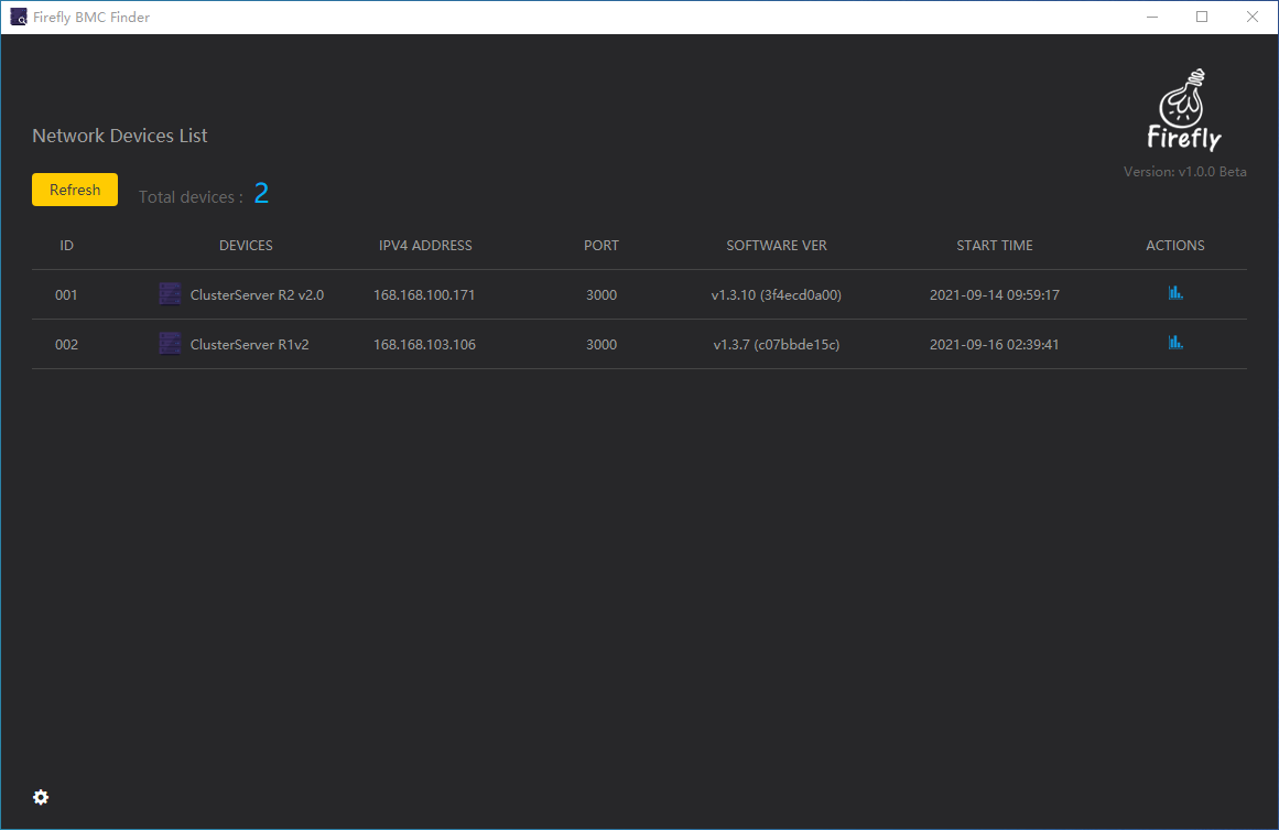
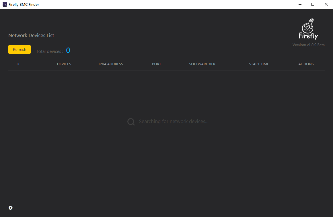
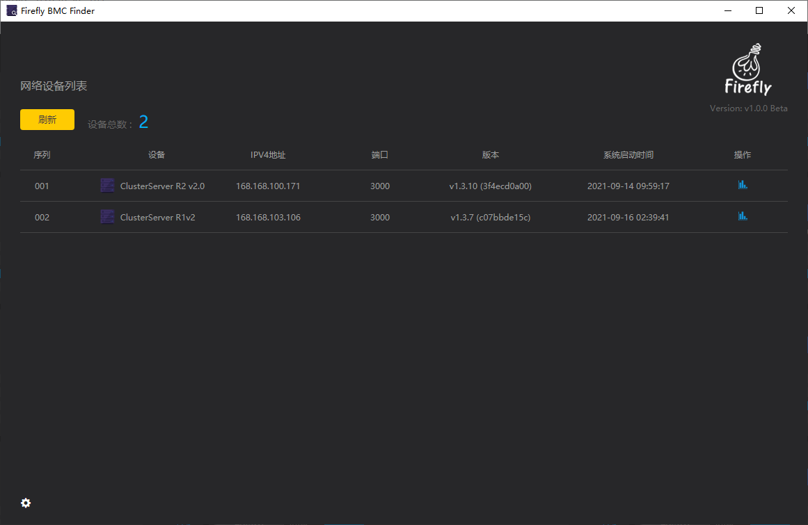
After the application is loaded, it will scan the LAN once by default, get all the IP addresses of BMC management system under the LAN and generate a list of items to be presented in the UI of the software, as shown in the picture.
The list items of the UI interface include the following information.
Total devices: Total number of list items
ID: ID number
Devices: Cluster server name
IPV4 ADDRESS: IP address number
PORT: IP port number
SOFTWARE VER: BMC management system version
START TIME: system opening time
ACTIONS: Access to the BMC management system’s
 Icon link
The information provided by the list item can be accessed by clicking on the  icon link at the corresponding list item to open an external browser and go directly to the login page of the corresponding BMC management system.
(3). Refreshing the BMC management system
After opening the tool, an automatic refresh is performed by default, and a manual refresh can be done by clicking the button  . If no BMC management system IP address is found after refreshing, you need to check whether the cluster server is on, whether the network interface is connected, whether the network is in the same LAN, etc.
If the tool does not find any BMC management system IP address after scanning the LAN, there is no list item generated in the software UI interface and the message “Searching for network devices…” is presented. “ message, as shown in the figure.
(4). Tool settings
Click the  icon in the left corner of the BMC Scan Tool to access the settings screen, as shown in the figure.
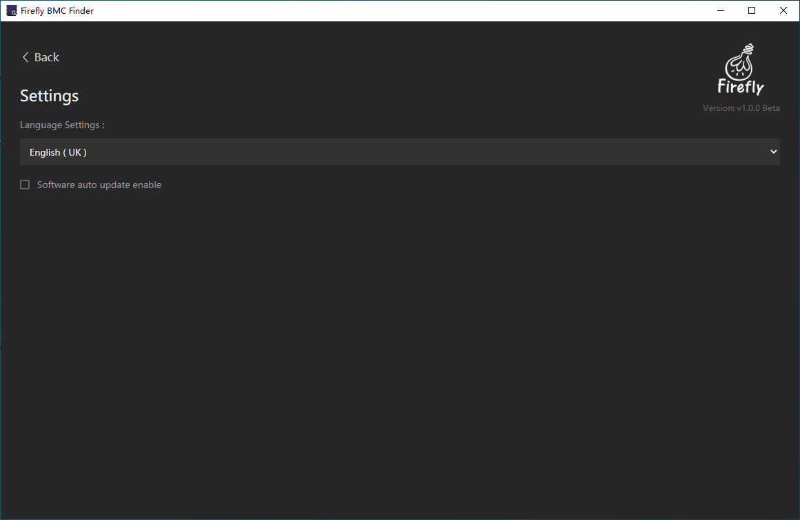
The setup interface currently supports Chinese and English language switching, and whether the software automatically checks for updates online.
The Chinese language interface is shown in the figure below.
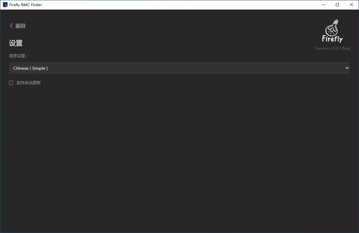
For more information about Firefly, you can click on the Logo in the upper right corner to enter the Firefly website for further information.