3. MaskRom mode
For an introduction to boot mode, please refer to the chapter Introduction to Upgrading Firmware
3.1. Introduction
MaskRom mode is the last line of defense against bricked devices. Forcibly entering MaskRom involves hardware operations and has certain risks. Therefore, you can only try MaskRom mode if the device cannot enter Loader mode.
CT36L Introduction
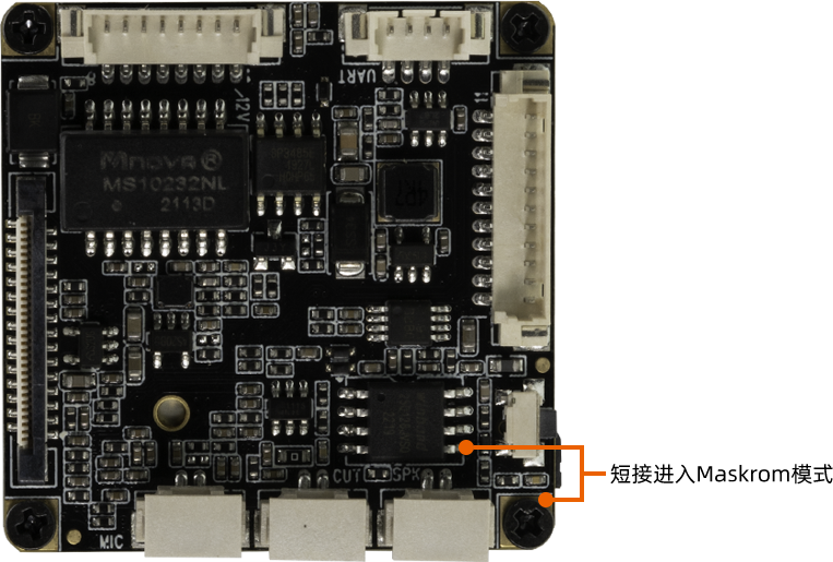
The principle of entering MaskRom is to artificially short-circuit the data pin of SPI FLASH with the ground wire. The system will think that the SPI FLASH data is wrong and clear the SPI FLASH data.
CT36B Introduction
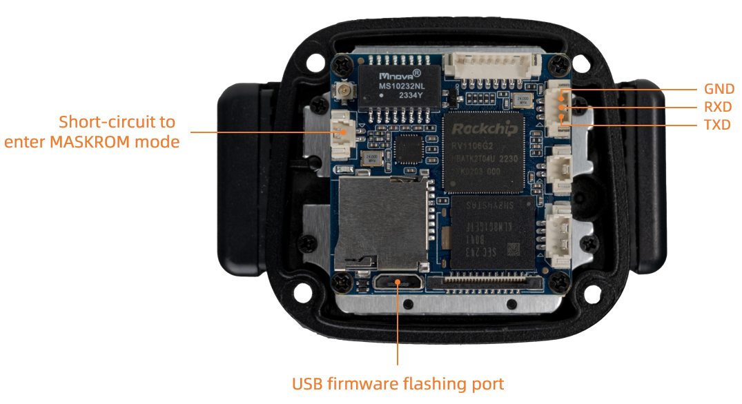
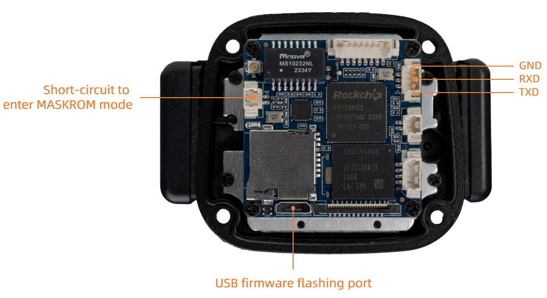
The principle of entering MaskRom is to artificially short-circuit the EMMC data pin and the ground wire. The system will think that the EMMC data is wrong and clear the EMMC data.
**Please read carefully and operate with caution! **
3.1.1. The software enters MaskRom mode
When the device system can be started and running normally
The steps are as follows:
Unplug the device from the power supply
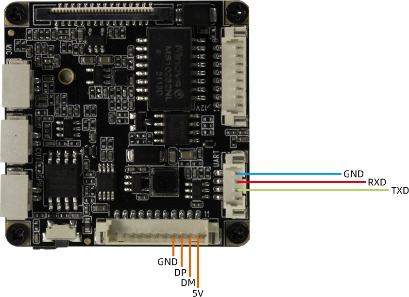
Connect the device to the serial port. The default baud rate of the serial port is
115200Connect the USB data cable to the device and connect it to the USB port of the computer.
CT36L hardware wiring diagram is as follows:

CT36B hardware wiring diagram is as follows:

Enter the command in the serial terminal to enter MaskRom mode.
reboot loader
3.1.2. Hardware enters MaskRom mode
When the device system is damaged and cannot operate normally, hardware operations need to be performed to force the device into Maskrom mode.
Unplug the device from the power supply
Use tweezers to short-circuit the 5th pin of the SPI FLASH chip and GND, and keep it there until the power supply is connected.
CT36L hardware wiring diagram is as follows:

CT36L hardware wiring diagram is as follows:

Connect the USB data cable to the computer USB interface. At this time, the device automatically enters MaskRom mode.
At this point the device will enter MaskRom mode.
