8. MIPI DSI Use
8.1. Kernel configuration
Add the following configuration in arch/arm/configs/firefly-rk3288_defconfig.
CONFIG_LCD_MIPI=y
CONFIG_MIPI_DSI=y
CONFIG_RK32_MIPI_DSI=y
8.2. LCD pins configuration
Modify the child node “power_ctr” of “lcdc0” in path arch/arm/boot/dts/firefly-rk3288.dts. There are power enable pin “lcd_en”, chip select pin “lcd_cs”, reset pin “lcd_rst”. You can modify those configuration according to the LCD. For example:
power_ctr: power_ctr {
         rockchip,debug = <0>;
         lcd_en:lcd_en {
             rockchip,power_type = <GPIO>;
             gpios = <&gpio7 GPIO_A3 GPIO_ACTIVE_HIGH>;
             rockchip,delay = <10>;
         };

         lcd_cs:lcd_cs {
             rockchip,power_type = <GPIO>;
             gpios = <&gpio7 GPIO_A4 GPIO_ACTIVE_HIGH>;
             rockchip,delay = <10>;
         };

         /*lcd_rst:lcd_rst {
             rockchip,power_type = <GPIO>;
             gpios = <&gpio3 GPIO_D6 GPIO_ACTIVE_HIGH>;
             rockchip,delay = <5>;
         };*/
    }
8.3. Driver configuration
8.3.1. Add a new dts file
Add a new dts file in the path arch/arm/boot/dts/, such as lcd-xxx-mipi.dtsi
8.3.2. Include the dts file
Include the dts file you add in first step in path arch/arm/boot/dts/firefly-rk3288.dts. If there have included other display’s DTS files, please make them as annotation.
8.3.3. Add backlight configuration
Add backlight configuration in lcd-xxx-mipi.dtsi, for example:
backlight {
       compatible = "pwm-backlight";
       pwms = <&pwm1 0 10000>;
       rockchip,pwm_id= <1>;
       /* | dark(255-221) | light scale(220-0) | , scale_div=255*/
       brightness-levels = </*255 254 253 252 251 250 249 248 247 246 245 244 243 242 241 240 239 238 237 236 235 234 233 232 231 230 229 228 227 226 225
224 223 222 221 */
220 219 218 217 216 215 214 213 212 211 210 209 208 207 206 205 204 203 202 201 200 199 198 197 196 195 194 193 192 191 190 189 188 187
186 185 184 183 182 181 180 179 178 177 176 175 174 173 172 171 170 169 168 167 166 165 164 163 162 161 160 159 158 157 156 155 154 153 152 151 150 149
148 147 146 145 144 143 142 141 140 139 138 137 136 135 134 133 132 131 130 129 128 127 126 125 124 123 122 121 120 119 118 117 116 115 114 113 112 111
110 109 108 107 106 105 104 103 102 101 100 99 98 97 96 95 94 93 92 91 90 89 88 87 86 85 84 83 82 81 80 79 78 77 76 75 74 73 72 71 70 69 68 67 66 65 64
63 62 61 60 59 58 57 56 55 54 53 52 51 50 49 48 47 46 45 44 43 42 41 40 39 38 37 36 35 34 33 32 31 30 29 28 27 26 25 24 23 22 21 20 19 18 17 16 15 14 13
12 11 10 9 8 7 6 5 4 3 2 1 0>;
       default-brightness-level = <128>;
       enable-gpios = <&gpio8 GPIO_A6 GPIO_ACTIVE_HIGH>;
};
Prorerty
pwms: the attribute of PWM. The Firelfy-RK3288 use pwm1. 10000 is the frequency of PWM.
brightness-level: array for back light, the max value is 255. The configuration of dark and light area
default-brightness-level: default brightness, the range of this value is 0~255.
enable-gpios: the enable pin of back light.
See the documentations in the follow path for more information: Documentation/devicetree/bindings/video/backlight/pwm-backlight.txt.
8.3.4. Configure information of MIPI
configure information of MIPI, for example:
disp_mipi_init: mipi_dsi_init{
    compatible = "rockchip,mipi_dsi_init";
    rockchip,screen_init    = <1>;
    rockchip,dsi_lane       = <4>;
    rockchip,dsi_hs_clk     = <1000>;
    rockchip,mipi_dsi_num   = <1>;
};
Prorerty
rockchip,screen_init: the value of 0 means without special instruction while initial. The value of 1 means need the special instruction to initial the LCD display.
rockchip,dsi_lane: the number of lane.
rockchip,dsi_hs_clk: the value of hsclk.
rockchip,mipi_dsi_num:the number of DSI interface, single channel is 1, dual channel is 2.
See the documentation of the follow path for more information:
Documentation/devicetree/bindings/video/rockchip_mipidsi_lcd.txt
8.3.5. The configuration of initial instructions
It will need the special instructions to initial the When the value of “rockchip,screen_init” is set to 1.
rockchip,cmd_debug: Set this value to 1 and you will get the debug information from the debug serial.
rockchip,on-cmdsXX: the information of each instruction.
rockchip,cmd_type:the mode for data transfer. PDT mode or HSDT mode.
rockchip,dsi_id:The DSI interface for instructions transfer. If this value is set to 0 means using the DSI0(it’s the left side of the display while dual lane MIPI display ) for instruction transfer.If this value is set to1 means using the DSI1(it’s the right side of the display while dual lane MIPI display ) for instruction transfer. This value is set to 2 means using both the DSI0 and DSI1 for instruction transfer.
rockchip,cmd:the sequence of the instructions. The first Byte is the DSI data type, the second Byte is the RGE. The rest are the instructions.
rockchip,cmd_delay:the delay after sending instructions. The unit is ms.
8.3.6. The configuration of display sequence
Configure the time sequence in disp_timings node.
screen-type: Display type. If the MIPI display use single lane, the display type is SCREEN_MIPI. If the MIPI display use dual lanes, the display type is SCREEN_DUAL_MIPI,SCREEN_MIPI.
lvds-format: Independent options.
out-face: color configuration, it can be OUT-P888(24 bits), OUT_P666(18 bits) or OUT_P565(16 bits).
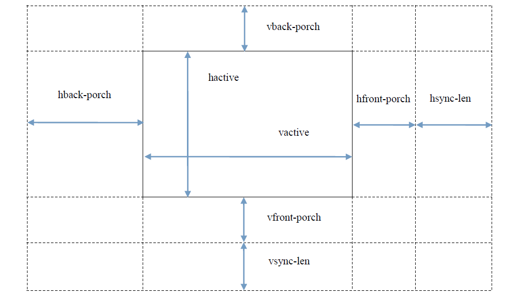
clock-frequency: clock of the LCD, measure by Hz. As to other timing’s attribute, you can take a look at this picture.

8.3.7. Dsihost configuration
If you using Double MIPI, enable the dsihost0 and dsihost1, for example:
&dsihost0 {
    status = "okay";
};
&dsihost1 {
    status = "okay";
};
If you using single MIPI, enable the dsihost0, for example:
&dsihost0 {
    status = "okay";
};
